Electronic winch monitoring system

a winch and electronic technology, applied in the direction of winding mechanisms, hoisting equipment, etc., can solve the problem that the control system does not provide all the features sometimes desired

Active Publication Date: 2005-04-07
PACCAR INC
View PDF37 Cites 101 Cited by
  • Summary
  • Abstract
  • Description
  • Claims
  • Application Information

AI Technical Summary

Benefits of technology

The present invention disclosed and claimed herein comprises, in one aspect thereof, an electronic winch monitoring system for a winch mechanism including a gearbox establishing a driving connection of predetermined fixed ratio between a rotatable input shaft and a rotatable output shaft, a primary brake including a plurality of interleaved friction plates and spacer plates operatively connected to the input shaft for selectively resisting rotational motion of the input shaft when activated, a rotatable winch drum operatively connected to the output shaft to rotate therewith for selectively winding on and winding off cable stored on the drum to hoist and lower loads, respectively, and an auxiliary brake including a plurality of interleaved friction plates and spacer plates operatively connected to the output shaft for selectively resisting rotational motion of the winch drum when activated by reducing a pressure in a brake release hydraulic circuit. The electronic winch monitoring system comprises an input speed sensor for

Problems solved by technology

These control systems do not provide all features sometime

Method used


Image

  • Electronic winch monitoring system
  • Electronic winch monitoring system
  • Electronic winch monitoring system

Examples


Embodiment Construction

The current invention is described below in greater detail with reference to certain preferred embodiments illustrated in the accompanying drawings.

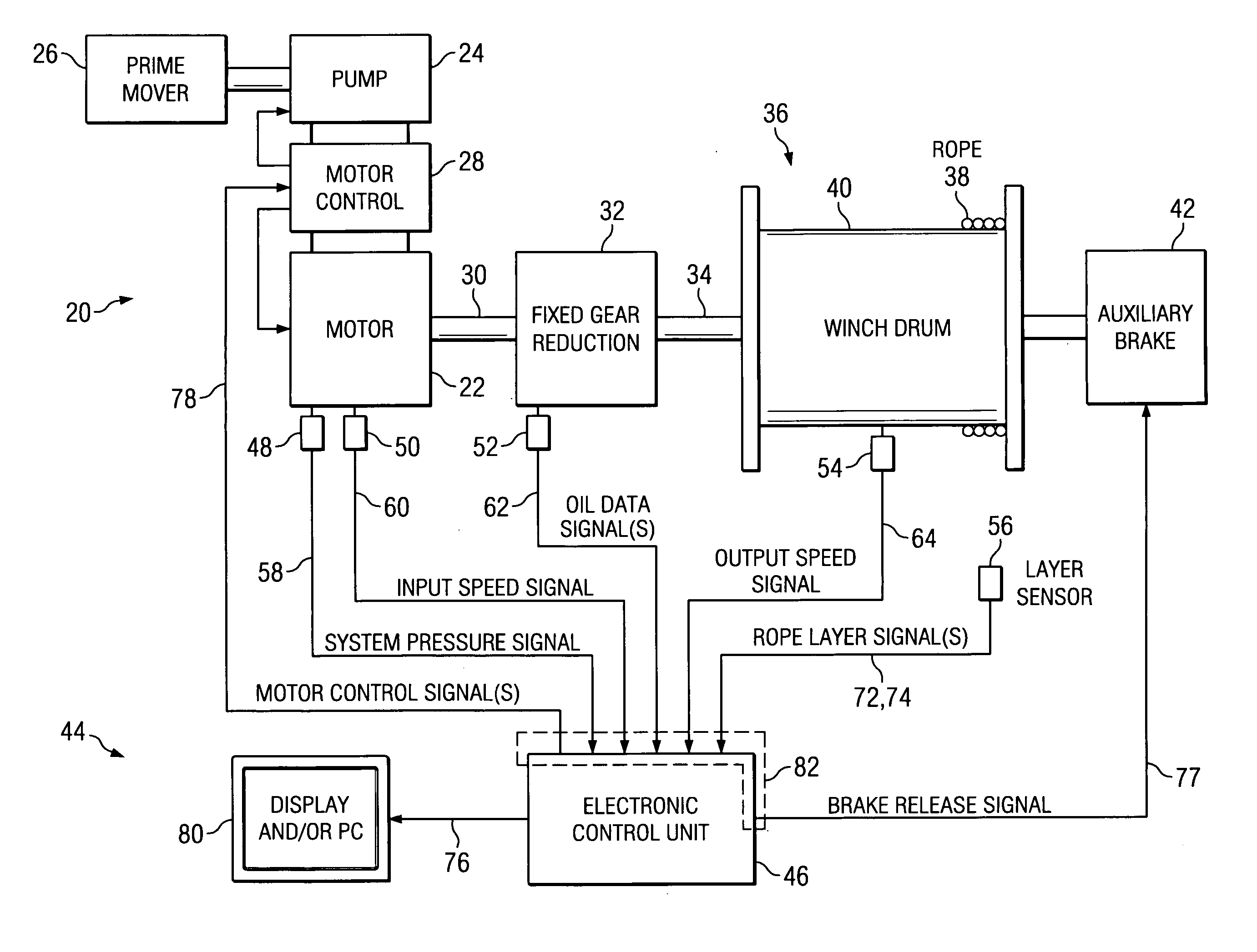
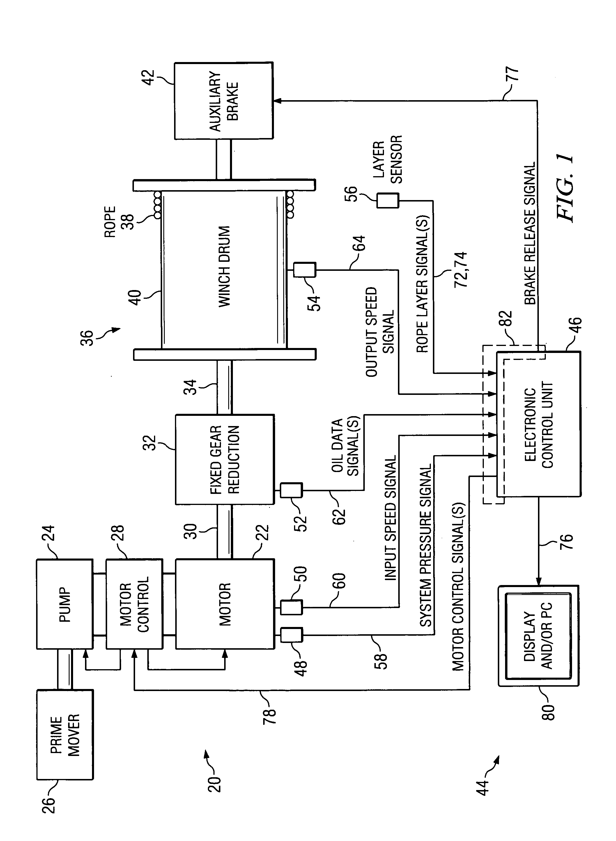
Referring now to FIG. 1, there is illustrated a schematic diagram of a winch mechanism equipped with an electronic winch monitoring system in accordance with one embodiment. A winch mechanism 20 includes a hydraulic motor 22 which receives hydraulic fluid from a hydraulic pump 24 powered by an internal combustion engine or other prime mover 26. Typically, the motor 22 and the pump 24 will be of the variable displacement type. The hydraulic motor 22 and the pump 24 may be connected to one another in either a closed-loop (i.e., hydrostatic) configuration or in an open-loop configuration, depending upon the application. A motor control unit 28 controls the speed, torque and direction of the motor 22 by changing the displacement of the motor and pump 24, and / or by modulating and redirecting the flow of hydraulic fluid from the pump to the...


PUM


Abstract

An electronic winch monitoring system for a winch having a fixed-ratio gearbox with input and output shafts, a winch drum connected to the output shaft, and an auxiliary brake connected to the output shaft activated by reducing the pressure in a brake release hydraulic circuit. The system comprises an input shaft speed sensor, an output shaft speed sensor, and an electronic control unit having a monitoring section and a brake control section. The monitoring section receives the speed signals, processes them to produce a calculated ratio of actual input to output shaft speeds, and produces a fault indication signal when the value of the difference between the calculated speed ratio and the fixed ratio exceeds a predetermined value. The brake control section, upon receiving the fault signal, reduces the hydraulic pressure in the brake circuit using a nonlinear pressure-time profile to engage the auxiliary brake and stop the winch drum.

Description

TECHNICAL FIELD OF THE INVENTION The current invention relates generally to a control apparatus for a winch mechanism. More particularly, this invention relates to a control apparatus having electrical sensors that provide signals indicative of winch operating parameters to an electronic control unit that provides electrical control signals in response thereto. BACKGROUND OF THE INVENTION Winch and control systems are known which measure various winch operating parameters and produce control responses thereto. Two such systems are described in U.S. Pat. Nos. 4,187,681 and 6,079,576. These control systems do not provide all features sometimes desired for the safe and efficient operation of a winch. A need therefore exists, for an improved electronic winch monitoring system which overcomes the disadvantages of conventional systems. SUMMARY OF THE INVENTION The present invention disclosed and claimed herein comprises, in one aspect thereof, an electronic winch monitoring system for...

Claims


Application Information

Patent Timeline
IPC IPC(8): B66D1/48
CPCB66D1/485B66D5/26B66D1/54
Inventor SANDERS, MARK E.JOHNSON, DAVID E.
Owner PACCAR INC
Why Eureka
Try Eureka