State detecting method and insulation resistance fall detector

a technology of state detection and fall detector, which is applied in the direction of testing circuits, instruments, electric devices, etc., can solve the problems of whether the earth detecting circuit itself is in a failed state or a normal state that cannot be disadvantageously detected, and achieve the effect of simple structur

Active Publication Date: 2005-04-07
YAZAKI CORP
View PDF1 Cites 23 Cited by
  • Summary
  • Abstract
  • Description
  • Claims
  • Application Information

AI Technical Summary

Benefits of technology

According to the invention, since a simple structure that the duty of the pulse signal is varied enables the pulse width...

Problems solved by technology

However, in the above-described earth detecting circuit, whether the earth detecting ...

Method used


Image

  • State detecting method and insulation resistance fall detector
  • State detecting method and insulation resistance fall detector
  • State detecting method and insulation resistance fall detector

Examples


Embodiment Construction

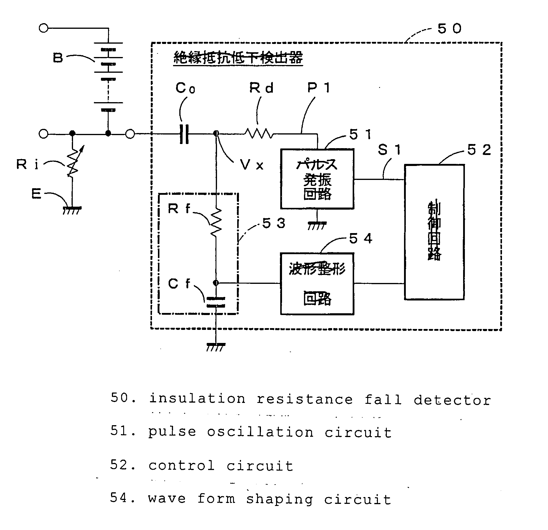
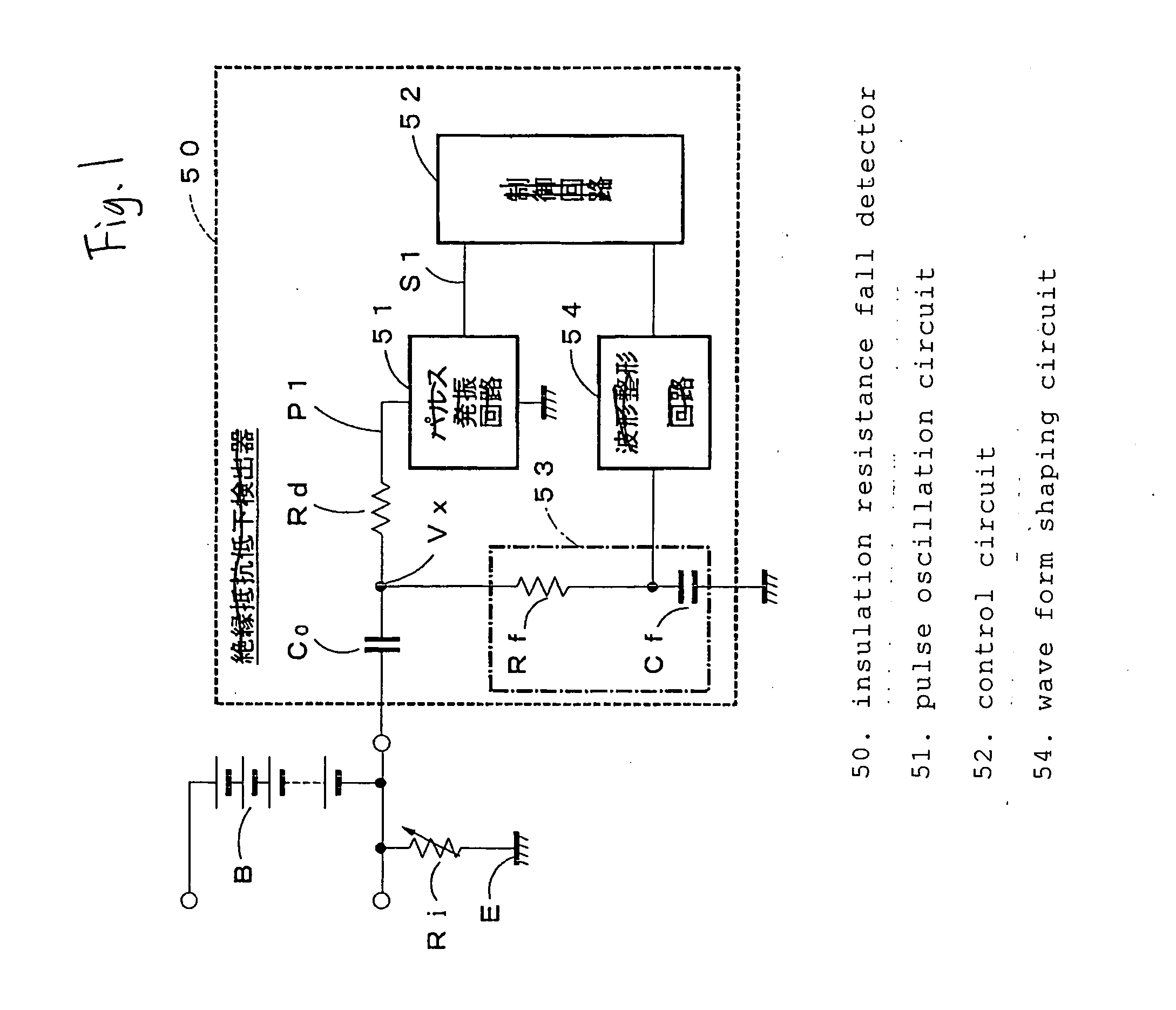
Now, a state detecting method and an insulation resistance fall detector according to the present invention will be described by referring to the drawings. FIG. 1 is a circuit diagram showing one embodiment of the insulation resistance fall detector in which the state detecting method according to the present invention is carried out. As shown in FIG. 1, the insulation resistance fall detector 50 includes a detection resistance Rd connected in series to an insulation resistance Ri between a battery group B as a DC power source and a vehicle body E and a coupling condenser Co for interrupting a direct current provided between the insulation resistance Ri and the detection resistance Rd. Further, in a serial circuit having the insulation resistance Ri, the coupling condenser Co and the detection resistance Rd, a pulse oscillation circuit 51 (a pulse signal applying unit) for applying a rectangular wave pulse signal P1 of a predetermined peak value is provided. Here, the peak value me...


PUM


Abstract

A method of detecting a state of an insulation resistance fall detector that includes: a detection resistance connected in series to an insulation resistance between a vehicle body and a power source; a condenser provided between the insulation resistance and the detection resistance; a pulse signal applying unit that applies a pulse signal to a serial circuit constituted by the insulation resistance, the condenser and the detection resistance; a low pass filter that filters a voltage of a connecting point between the coupling condenser and the detection resistance; and a fall detecting unit that detects a fall of the insulation resistance on the basis of the output of the filter, the method comprising the steps of: varying a pulse width of the pulse signal; and detecting the state of the insulation resistance fall detector on the basis of the output of the filter when the pulse width is varied.

Description

BACKGROUND OF THE INVENTION The present invention relates to a state detecting method for detecting the state of an insulation resistance detecting circuit for detecting an insulation resistance between a vehicle body and a DC power source and an insulation resistance fall detector in which the state detecting method is carried out. Usually, as the above-described insulation resistance fall detector, an earth detecting circuit of an electric motor vehicle, which is disclosed in, for instance, Patent Document 1 is exemplified. The earth detecting circuit serves to detect an earth to a vehicle body E from a battery group B, as shown in FIGS. 5 and 6, in the travel driving circuit system A of the electric motor vehicle comprising the battery group B provided as a high voltage DC power source (for instance, 200 to 300 V), an inverter 2 as a DC-AC converter for converting a direct current fed through a plus bus bar 4 as an anode DC feeder and a minus bus bar 5 as a cathode DC feeder fr...

Claims


Application Information

Patent Timeline
IPC IPC(8): G01R31/02B60L3/00G01N27/414G01R27/02G01R27/18G01R35/00
CPCG01R35/00G01R27/18H02H3/17H02H3/044
Inventor YAMAMOTO, KOUICHIISHIKAWA, SATOSHI
Owner YAZAKI CORP
Why Eureka
Try Eureka