Method and apparatus for magnetizing a permanent magnet

a permanent magnet and magnetizing technology, applied in the field of methods and apparatus for magnetizing a permanent magnet, can solve the problems of difficult fabrication of long lengths of large cross-section rectangular wires, complex and expensive standard manufacturing methods of such imaging systems, and often mechanical and electrical weakening of joints

Inactive Publication Date: 2005-04-07
GENERAL ELECTRIC CO
View PDF24 Cites 27 Cited by
  • Summary
  • Abstract
  • Description
  • Claims
  • Application Information

AI Technical Summary

Problems solved by technology

Therefore, the standard manufacturing method of such imaging systems is complex and expensive because it requires a special robot and / or extreme precautions.
Because it is difficult to fabricate long lengths of large cross-section rectangular wires, numerous short lengths of wire are joined together to make the coil.
These joints are frequently mechanically and electrically weak.
Also, for thick wire winding, the layer to layer transition is difficult.
These transitions often result in corner to corner contact which may damage insulation and result in a short during operation.
Further, the transitions often result in a lower packing factor, losing a ¼ turn or more at the end of each layer.
An additional issue with the conventional pulsed magnetic coil is Joule heating from the pulse.
However, the passage of current during the pulse typically heats the coil above 77 K, resulting in a tremendous increase in resistivity.

Method used


Image

  • Method and apparatus for magnetizing a permanent magnet
  • Method and apparatus for magnetizing a permanent magnet
  • Method and apparatus for magnetizing a permanent magnet

Examples


Embodiment Construction

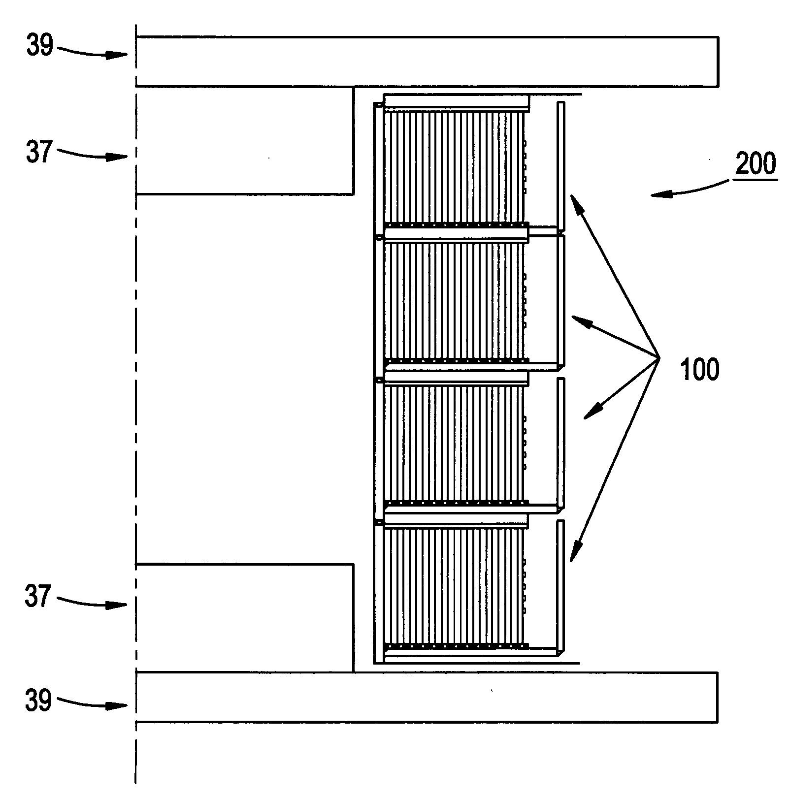
[0019] The present inventors have realized that the manufacturing method of a permanent magnet may be simplified if the unmagnetized blocks of permanent magnet precursor material are first assembled to form a precursor body, and then the precursor body is magnetized to form the permanent magnet body. Magnetizing the precursor alloy body after assembling unmagnetized blocks together simplifies the assembly process since the unmagnetized blocks are easier to handle during assembly. Special precautions need not be taken to prevent the blocks from demagnetizing if blocks of unmagnetized (or even partially magnetized) material are assembled. Furthermore, improved field homogeneity and reduced shimming time may be achieved by machining the precursor body into a desired shape for use in an imaging system prior to magnetizing the precursor body. Since the precursor body is unmagnetized, it may be readily machined into a desired shape without concern that it would become demagnetized during ...


PUM

PropertyMeasurementUnit
widthaaaaaaaaaa
widthaaaaaaaaaa
widthaaaaaaaaaa

Abstract

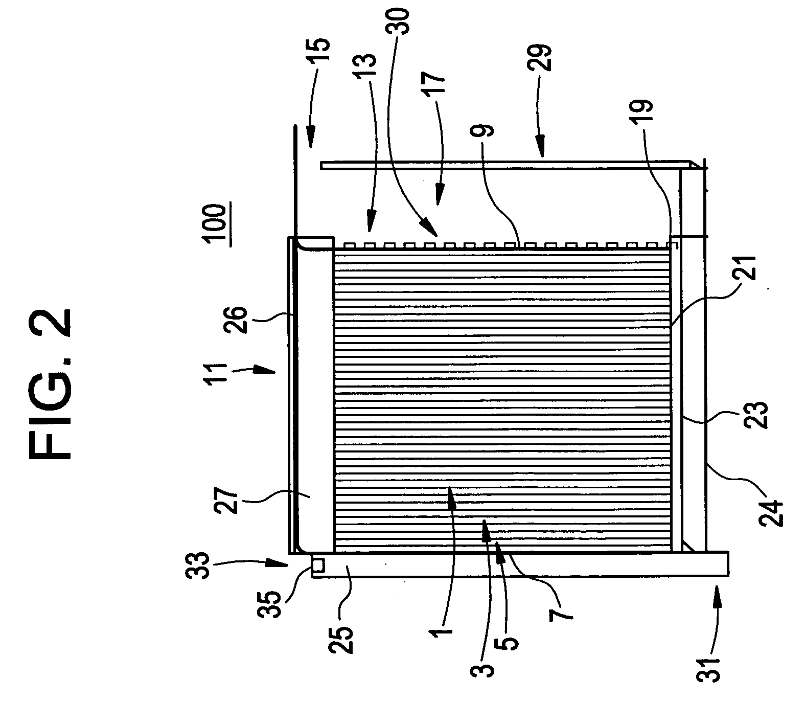
A magnetizing coil unit and a method of making a magnetizing coil unit is provided. The coil includes a solenoid coil having a coiled copper sheet in which the width of the copper sheet is equal to the height of the solenoid coil. A magnetizing assembly includes a plurality of magnetizing coil units.

Description

BACKGROUND OF THE INVENTION [0001] This invention relates generally to methods and apparatus for magnetizing a permanent magnet, and specifically to magnetizing a magnet used in a magnetic resonance imaging (MRI) system. [0002] There are various magnetic imaging systems which utilize permanent magnets. These systems include magnetic resonance imaging (MRI), magnetic resonance therapy (MRT) and nuclear magnetic resonance (NMR) systems. MRI systems are used to image a portion of a patient's body. MRT systems are generally smaller and are used to monitor the placement of a surgical instrument inside the patient's body. NMR systems are used to detect a signal from a material being imaged to determine the composition of the material. [0003] These systems often utilize two or more permanent magnets directly attached to a support, frequently called a yoke. An imaging volume is providing between the magnets. A person or material is placed into an imaging volume and an image or signal is det...

Claims


Application Information

Patent Timeline
Patent Type & Authority Applications(United States)
IPC IPC(8): A61B5/055G01R33/383H01F13/00
CPCY10T29/49071H01F13/003
Inventor LASKARIS, EVANGELOS TRIFONTHOMPSON, PAUL SHADFORTHLI, LIANGAMM, KATHLEEN MELANIEAKSEL, BULENTPALMO, MICHAEL ANTHONY JR.
Owner GENERAL ELECTRIC CO
Why Eureka
Try Eureka