Method and device for immersion lithography

Inactive Publication Date: 2005-04-07
MICRONIC LASER SYST AB
View PDF9 Cites 709 Cited by
  • Summary
  • Abstract
  • Description
  • Claims
  • Application Information

AI Technical Summary

Benefits of technology

[0007] Accordingly, it is an object of the present invention to provide a method for patterning a wor

Problems solved by technology

Optical mask making tools typically use excimer lasers as their light source, and are therefore restricted in the wavelengths they can use.
Adapting optical mask makers to use 193 nm is quite difficult for several reasons: (1) the choice of optical materials is restricted, because most optical material absorb 193 nm light.
Optical coatings also present challenges.
This makes the opto-mechanical design more cumbersome, and makes alignment and measurement quite difficult.
(3) 193 nm lasers are not as reliable or stable as 248 nm lasers, and their ener

Method used


Image

  • Method and device for immersion lithography
  • Method and device for immersion lithography
  • Method and device for immersion lithography

Examples


Embodiment Construction

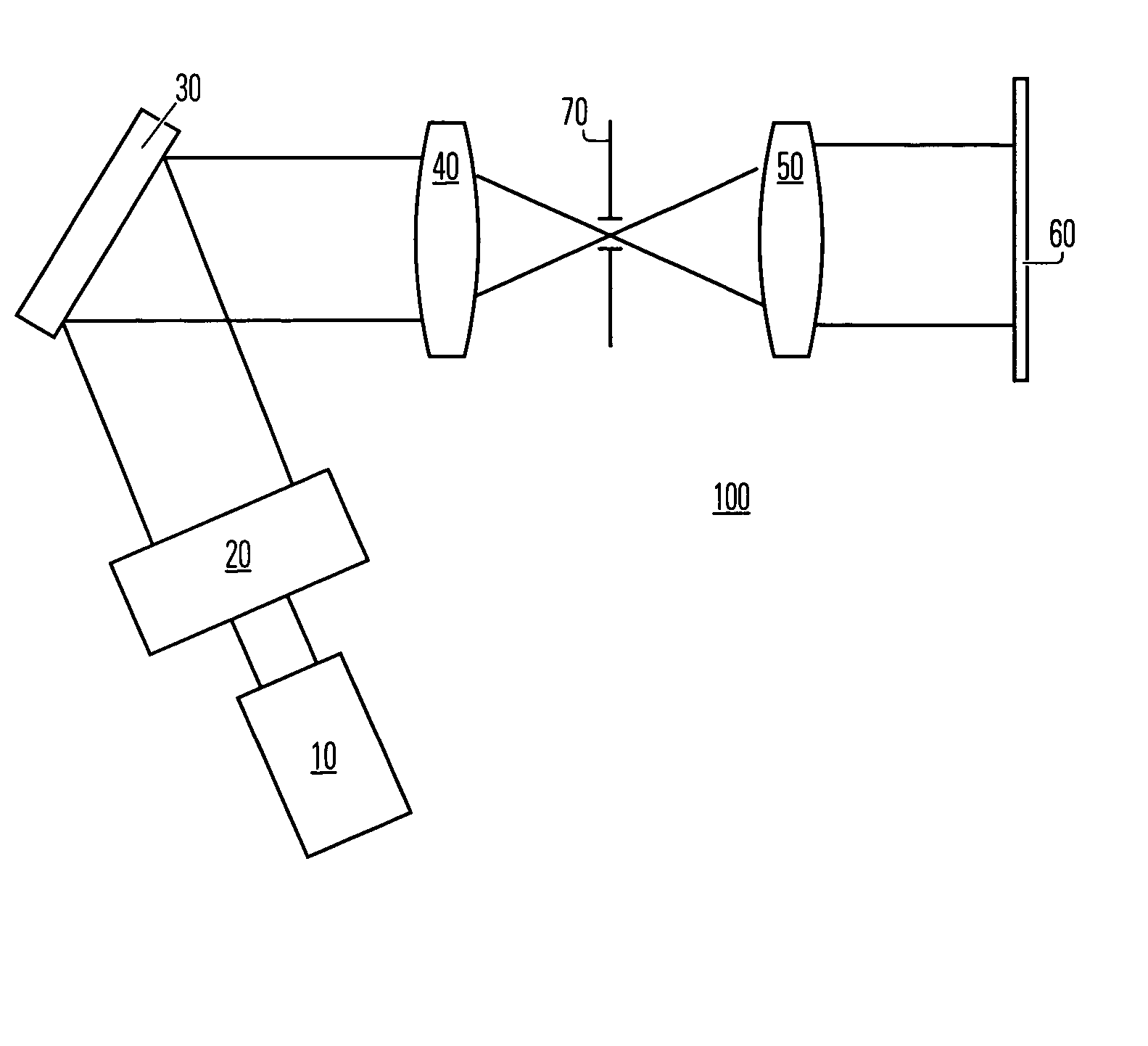
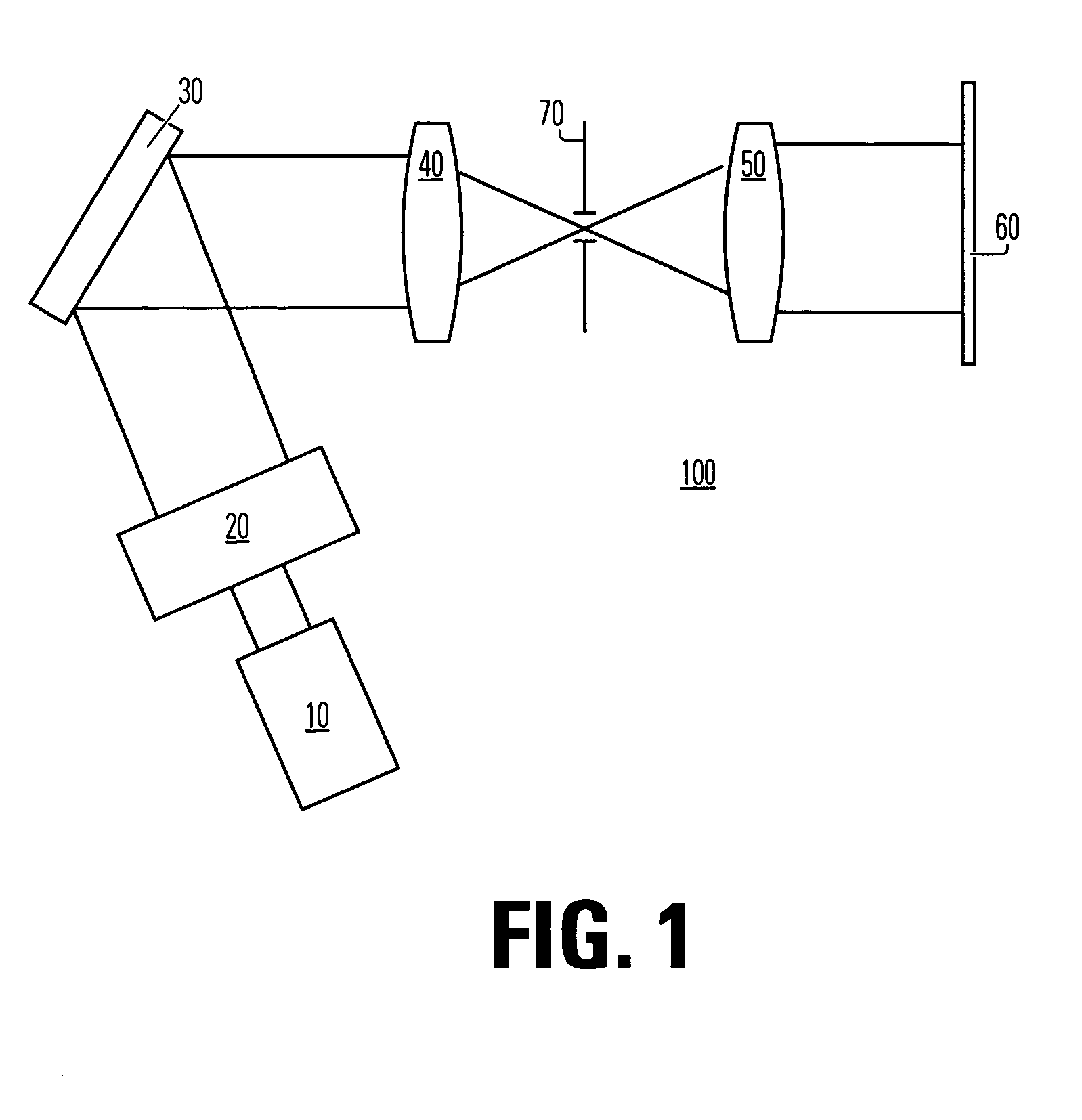
[0014]FIG. 1 illustrates an embodiment of an apparatus 100 for patterning a work piece 60 according to prior art, into which the present invention could easily be inserted.

[0015] Said apparatus 100 comprising a source 10 for emitting electromagnetic radiation, an objective lens arrangement 50, a computer-controlled reticle 30, a beam conditioning arrangement 20, a spatial filter 70 in a fourier plane, a Fourier lens arrangement 40 and said work piece 60.

[0016] The source 10 may emit radiation in the range of wavelengths from infrared (IR), which is defined as 780 nm up to about 20 μm, to extreme ultraviolet (EUV), which in this application is defined as the range from 100 nm and down as far as the radiation is possible to be treated as electromagnetic radiation, i.e. reflected and focused by optical components. The source 10 emits radiation either pulsed or continuously. The emitted radiation from the continuous radiation source 10 can be formed into a pulsed radiation by means of...


PUM


Abstract

The present invention relates to an immersion lithographic system for patterning a work piece arranged at an image plane and covered at least partly with a layer sensitive to electromagnetic radiation. Said system comprising a source emitting electromagnetic radiation onto an object plane, a mask, adapted to receive and modulate said electromagnetic radiation at said object plane and to relay said electromagnetic radiation toward said work piece, and an immersion medium contacting at least a portion of a final lens of said lithographic system and a portion of said work piece, wherein an area of said contacting is restricted by capillary forces. The invention further relates to a method for patterning a workpiece.

Description

TECHNICAL FIELD [0001] The present invention relates in general to techniques for optical lithography, and in particular to a method for patterning a workpiece using immersion lithography. DESCRIPTION OF THE BACKGROUND ART [0002] When making a pattern on a workpiece, which workpiece could be integrated circuits, masks, reticles, flat panel displays, micro mechanical or micro optical devices and packaging devices, e.g. lead frames and MCM's, a pattern may be exposed in a positive photo resist. In case of producing a mask, the resist in the exposed areas is removed by a develop-and-etch process and, unprotected chromium is then dissolved by a chromium etchant. The result, a glass plate with a pattern in opaque chromium, is used as an optical contact or projection mask for production of a device layer pattern in flat panel displays or integrated circuits. [0003] The pattern generator could be any one of the types of commercially available laser pattern generators using acousto-optical ...

Claims


Application Information

Patent Timeline
IPC IPC(8): G03F7/20
CPCG03F7/70341G03F7/2041G03F7/20G03B27/00
Inventor CARROLL, ALLEN
Owner MICRONIC LASER SYST AB
Why Eureka
Try Eureka