Switching power converter and method of controlling output voltage thereof using predictive sensing of magnetic flux

a technology of predictive sensing and power converter, which is applied in the direction of dc-dc conversion, power conversion systems, instruments, etc., can solve the problems of increasing the cost and size of a power converter, increasing the cost and complexity of the feedback circuit, and reducing reliability and long-term stability. , to achieve the effect of improving immunity from parasitic phenomena

Active Publication Date: 2005-04-07
MICROCHIP TECH INC
View PDF3 Cites 123 Cited by
  • Summary
  • Abstract
  • Description
  • Claims
  • Application Information

AI Technical Summary

Benefits of technology

[0013] The above objective of controlling a switching power converter output entirely from the primary side with improved immunity from parasitic phenomena is achieved in a switching power converter apparatus and method. The power converter includes an integrator that generate a voltage corresponding to magnetic flux within a power magnetic element of the power converter. The integrator is coupled to a winding of the power magnetic element and integrates the voltage of the winding. A detection circuit detects an end of a half-cycle of post-conduction resonance that occurs in the power magnetic element subsequent to the energy level in the power magnetic falling to zero. The voltage of the integrator is stored at the end of a first post-conduction resonance half-cycle and is used to determine a sampling time prior to or equal to the start of a post-conduction resonance in a subsequent switching cycle of the power converter. At the sampling time, the auxiliary winding voltage is sampled and used to control a switch that energizes the power magnetic element.

Problems solved by technology

The feedback circuit typically raises the cost and size of a power converter significantly and also lowers reliability and long-term stability, as optocouplers change characteristics with age.
A primary power winding may be used as a sense winding, but due to the high voltages typically present at the power winding, deriving a feedback signal from the primary winding may raise the cost and complexity of the feedback circuit.
However, parasitic phenomena typically associated with magnetically coupled circuits cause error in the feedback signal that degrade voltage regulation performance.
All of the above parasitic phenomena reduce the accuracy of the above-described compensation scheme.
However, no prior art solution exists that provides a reliable and universal method that adapts to the values of the above-mentioned parasitic phenomena in order to accurately sense the voltage at the above-mentioned small constant magnetization current point in DCM power converters.

Method used


Image

  • Switching power converter and method of controlling output voltage thereof using predictive sensing of magnetic flux
  • Switching power converter and method of controlling output voltage thereof using predictive sensing of magnetic flux
  • Switching power converter and method of controlling output voltage thereof using predictive sensing of magnetic flux

Examples


Embodiment Construction

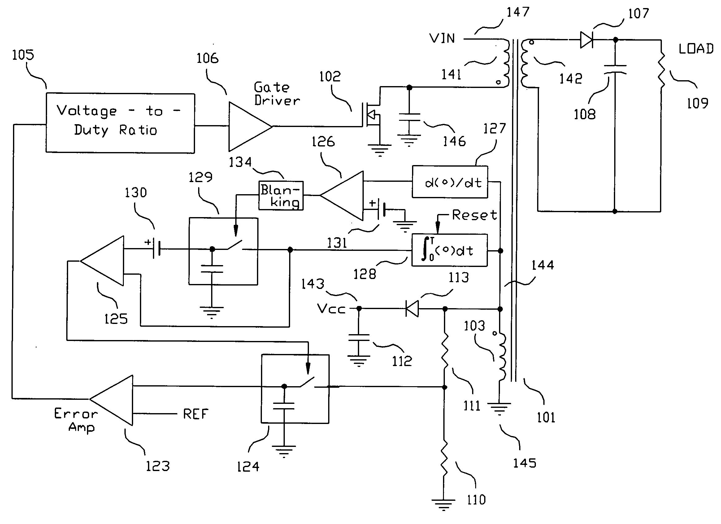
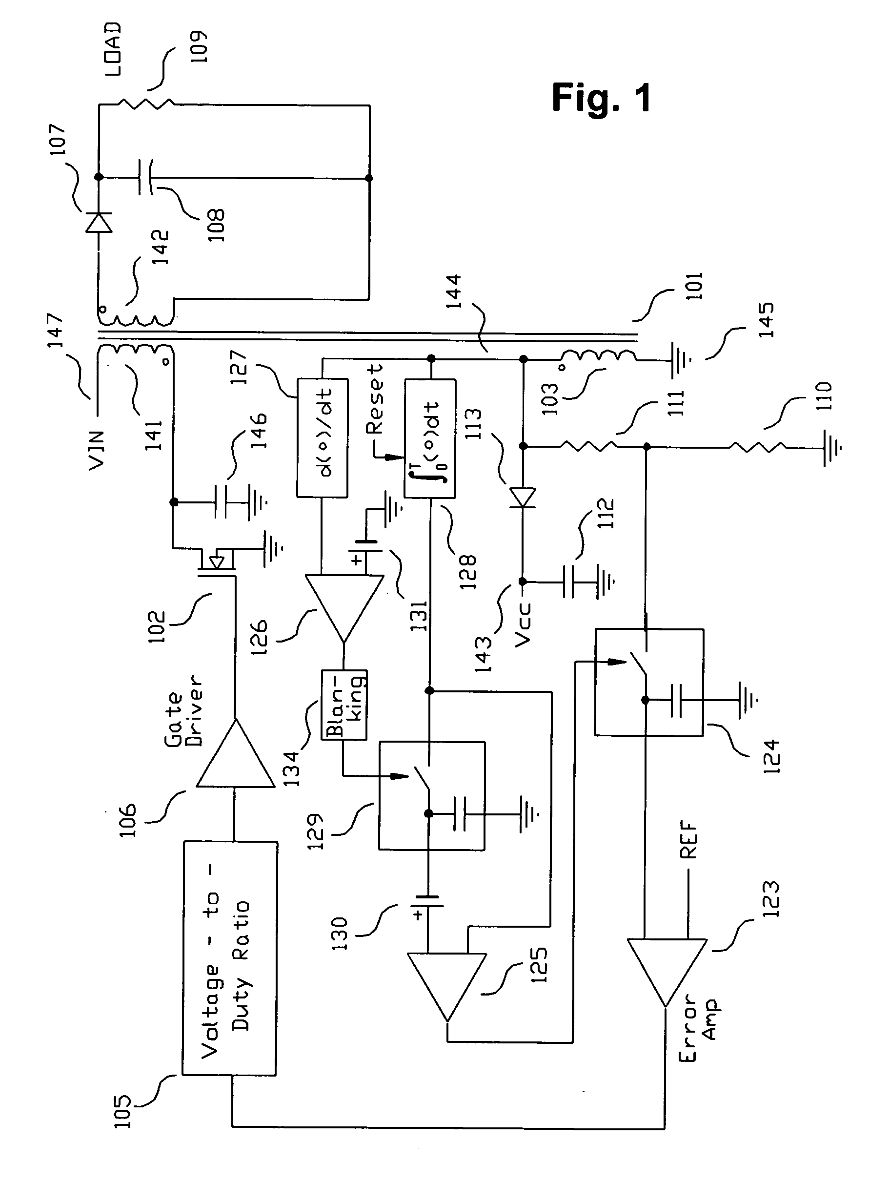
[0024] The present invention provides novel circuits and methods for controlling a power supply output voltage using predictive sensing of magnetic flux. As a result, the line and load regulation of a switching power converter can be improved by incorporating one or more aspects of the present invention. The present invention includes, alone or in combination, a unique sampling error amplifier with zero magnetization detection circuitry and unique pulse width modulator control circuits.

[0025]FIG. 1 shows a simplified block diagram of a first embodiment of the present invention. The switching configuration shown is a flyback converter topology. It includes a transformer 101 with a primary winding 141, a secondary winding 142, an auxiliary winding 103, a secondary rectifier 107 and a smoothing capacitor 108. A resistor 109 represents an output load of the flyback converter. A capacitor 146 represents total parasitic capacitance present at an input terminal of primary winding 141, inc...


PUM


Abstract

A switching power converter and method of controlling an output voltage thereof using predictive sensing of magnetic flux provides a low-cost switching power converter via primary-side control using a primary-side winding. The power converter has improved immunity to parasitic phenomena and other variations within the power converter components. An integrator is used to generate a voltage analog that represents magnetic flux within a power magnetic element via an integration of a voltage on a primary-side winding of the power magnetic element. A detection circuit detects the end of a half-cycle of post-conduction resonance that occurs in the power magnetic element subsequent to the energy level in the power magnetic element reaching zero. The voltage of the integrator is stored at the end of the post-conduction resonance half-cycle and is used to determine a sampling point prior to or equal to the start of post-conduction resonance in a subsequent switching cycle of the power converter (which is the predicted zero-energy storage point of the power magnetic element). The primary-side winding voltage is then sampled at the sampling point, providing an indication of the output voltage of the power converter. By predicting the zero-magnetic-energy storage point, the output voltage of a power converter operating in discontinuous or boundary conduction mode can be accurately controlled without being affected by parasitic phenomena or variations in circuit performance over time, input voltage and temperature.

Description

CROSS-REFERENCE TO RELATED APPLICATION [0001] This application is a Continuation-In-Part of U.S. patent application Ser. No. 10 / 677,439, filed Oct. 2, 2003 and from which it claims benefits under 35 U.S.C. §120. This application also claims the benefit of priority under 35 U.S.C. §119(e) of U.S. Provisional Application Ser. No. 60 / 534,515 filed Jan. 6, 2004.BACKGROUND OF THE INVENTION [0002] 1. Field of the Invention [0003] The present invention relates generally to power supplies, and more specifically to a method and apparatus for controlling a switching power converter entirely from the primary side of the power converter by predictive sensing of magnetic flux in a magnetic element. [0004] 2. Background of the Invention [0005] Electronic devices typically incorporate low voltage DC power supplies to operate internal circuitry by providing a constant output voltage from a wide variety of input sources. Switching power converters are in common use to provide a voltage regulated sou...

Claims


Application Information

Patent Timeline
Patent Type & Authority Applications(United States)
IPC IPC(8): H02M3/335
CPCH02M3/33523
Inventor MEDNIK, ALEXANDERSCHIE, DAVID CHALMERSNGUYEN, JAMES HUNGGU, WEI
Owner MICROCHIP TECH INC
Why Eureka
Try Eureka