Producing method for die coater and coating apparatus

a coating apparatus and die coating technology, applied in the direction of liquid surface applicators, pretreated surfaces, coatings, etc., can solve the problems of coating failure, painstaking cleaning after coating termination, liquid coating composition,

Inactive Publication Date: 2005-04-07
KONICA MINOLTA MEDICAL & GRAPHICS INC
View PDF6 Cites 12 Cited by
  • Summary
  • Abstract
  • Description
  • Claims
  • Application Information

AI Technical Summary

Problems solved by technology

Regarding an outer wall continuous with a lip section, when a flow rate is set at the start of coating and when coating is terminated, a liquid coating composition flows down along the outer wall continuous with the lip section, adheres to the outer wall, and then gets dry and solidifies, which makes cleaning after the termination of coating painstaking.
If the deposit grows to a certain extent in this way, the rate and the flow speed of a liquid coating composition vary at the deposit, which makes the flow of the liquid coating composition unstable, resulting in a coating failure and difficulty in production.
Documents 1 to 4 are so sophisticated as to allow it to prevent adherence of foreign materials by covering portions of a die coater, the portions coming in contact with a liquid coating composition, with a fluorine based resin, but these technologies have the following problem.
In a process of covering bars with a fluorine based resin for a bar, a baking process deteriorate the straightness of the bars, and when a die coater is produced having these bars mounted thereon, the gap of a slit section in the lateral direction of coating and the distance between the die coater and an object to be coated become uneven to lower the uniformity of thickness of a layer in the lateral direction of coating, which may have resulted in a fear that coating cannot be achieved.
However, in the case of a bar used for a die coater having a coating width exceeding 1 m, the influence of heat treatment in a fluorine based resin covering process is so significant that although a die coater produced having bars covered with the fluorine based resin is allowed to prevent coating failures due to deposition of a liquid coating composition, but the die-coater is not allowed to attain uniformity of layer thickness in the lateral direction of coating, thus only permitting coating that does not require a quality with uniformity of the coating layer thickness.

Method used


Image

  • Producing method for die coater and coating apparatus
  • Producing method for die coater and coating apparatus
  • Producing method for die coater and coating apparatus

Examples


example 1

A light-sensitive layer liquid coating composition containing organic silver was prepared based on the method described below.

<Light-Sensitive Layer Liquid Coating Composition>

<<Preparation of Silver Halide Emulsion A>>

Dissolved in 900 ml of water were 7.5 g of gelatin and 10 mg of potassium bromide, the resulting solution was maintained at 35° C. and the pH was adjusted to 3.0, thereafter, 370 ml of an aqueous solution containing 74 g of silver nitrate and 370 ml of an aqueous solution containing potassium bromide and potassium iodide at a mol ratio of (98 / 2), as well as an [Ir(NO)Cl6] salt in an amount of 1×10⁻⁶ mol per mol with respect to mol of silver, and rhodium chloride in an amount of 1×10⁻⁶ mol with respect to mol of silver were added employing a controlled double jet method while maintaining pAg at 7.7.

Thereafter, 4-hydroxy-6-methyl-1,3,3a,7-tetraazaindene was added and the pH of the resulting mixture was adjusted to 5 by the addition of NaOH, whereby c...

example 2

<Light-Sensitive Layer Liquid Coating Composition>

The light-sensitive layer liquid coating composition as prepared in Example 1 was employed.

<Preparation of Die Coater>

The surface protective layer liquid coating composition as prepared in Example 1 was employed.

<Preparation of Die Coater>

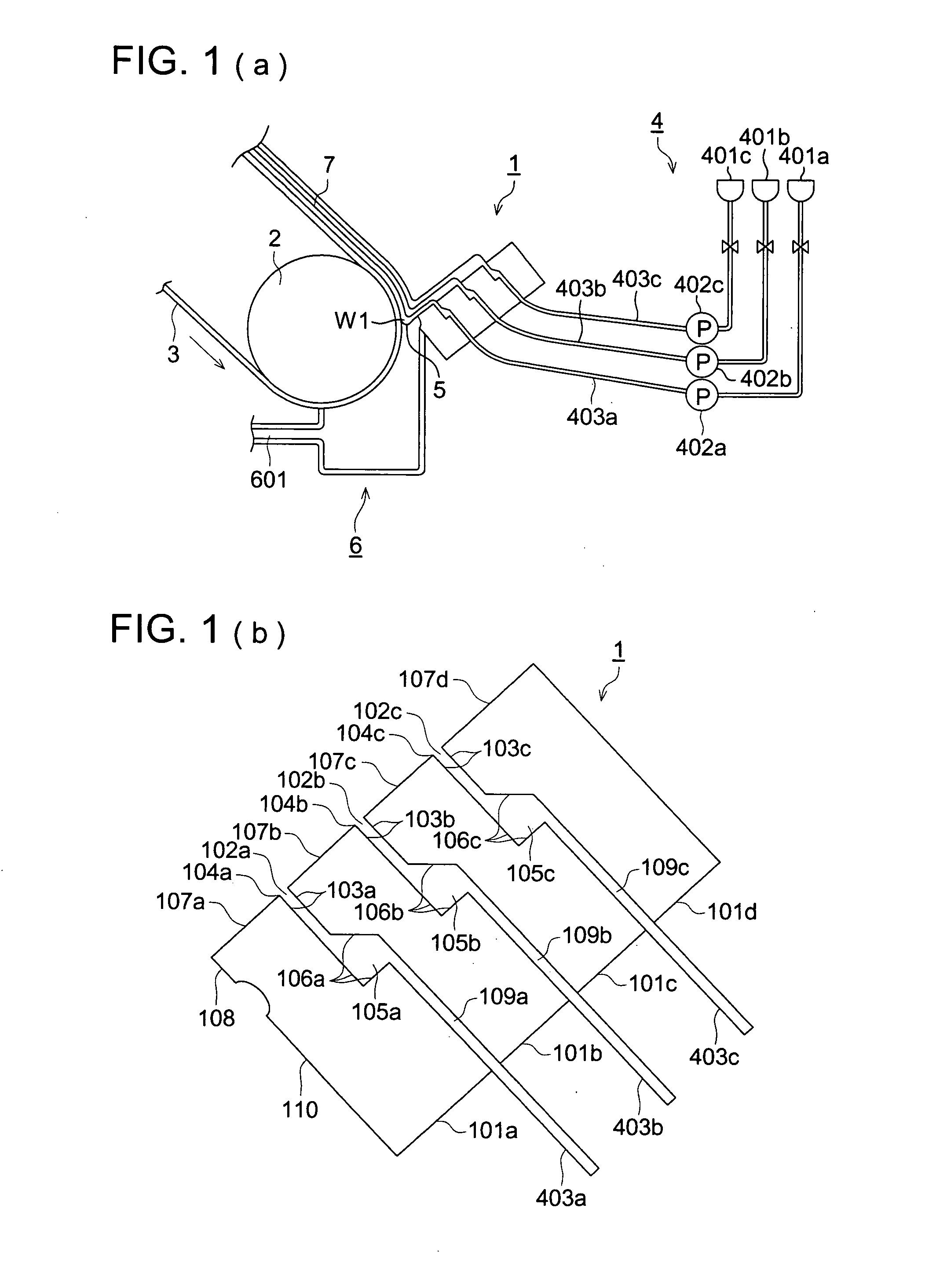
The slide type die coaters shown in FIG. 1 were prepared employing the method below and designated as 2-1-2-11.

When preparing, each of the 1,500 mm wide stainless steel (SUS 630) bars which constituted the slide type die coater was subjected to a grinding process to remove distortion caused by change of a preheating temperature and after the preheating as shown in Table 3. Thereafter, the portion in contact with a liquid coating composition was covered with a fluorine based resin by changing the temperature of the baking process, thereby producing bars, and these bars were assembled, whereby a slide type die coater was prepared.

As for all other condition, it was produced by t...

example 3

When producing the die coater 2-1 shown in Table 3 of Example 2, as shown in Table 5, except that the straightness of the surface in the direction of coating width after the surface coating process with a fluorine based resin was changed by grinding processing, the bar was produced on the same condition as Example 2, these bars were assembled to produce the die coater referred to as 3-1 to 3-7.

Incidentally, measurement of the thickness of fluorine based resin, surface roughness, and straightness was performed by the same method as Example 1.

TABLE 5Straightness (μm) ofDie Coaterportions covered withNo.fluorine based resin3-10.083-20.13-31.03-45.03-58.03-610.03-711.0

<Coating>

The produced slid type die coater 3-1 to 3-7 which was used for one year under normal temperature was used, coating and drying were performed for them on the same condition as an example 1, and samples 301-307 were produced.

<Evaluation>

To each obtained Samples 301-307, by the same method as an Ex...


PUM


Abstract

A method of producing a die coater structured with at least two bars so as to form a pocket section to extend a coating liquid in a coating width direction, a coating liquid supply port to supply a coating liquid to the pocket section, and a slit section to discharge a coating liquid from the pocket section to a material to be coated, wherein at least a part of a surface of the two bars coming in contact with a coating liquid is covered with a fluorine-based resin, the method comprises a covering process of covering a part of a surface of a bar coming in contact with a coating liquid with a fluorine-based resin; and a baking process of baking the fluorine-based resin covering the part of the surface of the bar at a temperature of 100 to 380° C.

Description

BACKGROUND OF THE INVENTION The present invention relates to a coating apparatus provided with a die coater having at least 2 bars mounted thereon and to a method of manufacturing the die coater, and specifically, relates to a coating apparatus provided with a die coater having at least 2 bars with an excellent cleaning ability mounted thereon and to a method of producing the die coater having at least 2 bars mounted thereon, wherein the coating apparatus causes few coating failures and achieves an excellent coating quality. In the prior art, as a method for coating a continuously running belt-shaped support or a base board (hereinafter, also referred to as “support”) with a liquid coating composition (for example, liquid coating compositions for subbing, overcoating, and a backside layer) for surface treatment of materials such as photographic photosensitive materials, heat development recording materials, abrasion recording materials, magnetic recording media, glass plates, stee...

Claims


Application Information

Patent Timeline
Patent Type & Authority Applications(United States)
IPC IPC(8): B05C5/00B05C5/02B05C9/06
CPCB05C5/007B05C9/06B05C5/0254B05C5/008
Inventor KAWABE, SHIGETOSHI
Owner KONICA MINOLTA MEDICAL & GRAPHICS INC
Why Eureka
Try Eureka