Ceramic substrate and method of manufacturing same

a technology of ceramic substrate and manufacturing method, which is applied in the field of ceramic substrate, can solve the problems that the assembly surface not only forms a cavity limitation, and achieve the effect of preventing overloading of ceramic substrate, easy and cost-effectiv

Inactive Publication Date: 2005-04-07
ROBERT BOSCH GMBH
View PDF4 Cites 5 Cited by
  • Summary
  • Abstract
  • Description
  • Claims
  • Application Information

AI Technical Summary

Benefits of technology

[0004] In a particularly advantageous application, the ceramic substrate according to the present invention is used as a membrane element of a pressure sensor or of a force sensor having piezoresistive resistors. For this purpose, the curved ceramic substrate according to the present invention is positioned in such a way that the pressure, i.e., the force to be measured, acts against the pre-stress of the ceramic substrate, caused by the curvature. In this application the ceramic substrate according to the present invention is advantageously positioned above a planar assembly surface, so that a cavity is included between the assembly surface and the ceramic substrate. In this case, the assembly surface not only forms a cavity limitation but is also used as a mechanical stop for the ceramic substrate due to its ability to withstand the pressure or force to be measured. An overload of the ceramic substrate is thus prevented. In addition, having such a composition of the sensor element, i.e., a planar carrier and the curved ceramic substrate according to the present invention, excessive stress, which may result in breakage, does not normally occur in the edge areas of the cavity. Since a mold ceramic is not required, such a sensor element having a cavity may be implemented in an easy and cost-effective manner.
[0005] Basically there are different possibilities for implementing a ceramic substrate having a defined curvature according to the present invention. In a particularly advantageous variant, at least two ceramic layers, having different but definedly set temperature coefficients of expansion (TCE), are positioned one upon the other and are permanently bonded together, e.g., by sintering. The curvature of the substrate may be very accurately predetermined in this way.
[0006] Through specific addition of crystallization nuclei to the precursor substances of the individual ceramic layers, for example, the temperature coefficients of expansion may be easily predetermined. A defined amount of baked ceramic in pulverized form may be simply added to the precursor substances of the individual ceramic layers for this purpose.

Problems solved by technology

In this case, the assembly surface not only forms a cavity limitation but is also used as a mechanical stop for the ceramic substrate due to its ability to withstand the pressure or force to be measured.

Method used


Image

  • Ceramic substrate and method of manufacturing same

Examples


Embodiment Construction

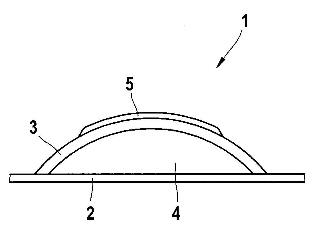
[0009] Pressure sensor element 1, depicted in the sole FIGURE, includes a planar carrier 2 which is designed to withstand the expected pressure without deformation. Carrier 2 may be formed from metal or from a ceramic substrate, for example. A membrane element 3 in the form of a ceramic substrate having a defined curvature according to the present invention is mounted on planar carrier 2, so that a cavity 4 is situated between carrier 2 and ceramic substrate 3. A circuit 5 is located on the side of ceramic substrate 3 facing away from cavity 4, the circuit including at least one piezoresistive resistor element which may be implemented using screen printing technology. The circuit including the piezoresistive resistor element may also be situated on the side of the ceramic substrate facing the cavity, where it is better protected against external effects.

[0010] Pressure sensor element 1 is positioned in such a way that the pressure to be measured acts against the pre-stress of membr...


PUM

PropertyMeasurementUnit
curvatureaaaaaaaaaa
temperature coefficients of expansionaaaaaaaaaa
compositionaaaaaaaaaa

Abstract

A ceramic substrate having a defined curvature and a method of its manufacture are described. For this purpose at least two ceramic layers having different defined temperature coefficients of expansion are positioned on top of one another and are permanently bonded together. A curved ceramic substrate may be advantageously utilized in micro-hybrid technology, in multilayer ceramic technology, or in hybrid technology, e.g., as a membrane element of a piezoresistive pressure sensor element.

Description

FIELD OF THE INVENTION [0001] The present invention relates to a ceramic substrate such as is used in micro-hybrid technology. BACKGROUND INFORMATION [0002] As a rule, such ceramic substrates are formed in several layers. For this purpose, homogeneous tape layers, i.e., tape layers having the same composition, are positioned on top of one another, laminated, and sintered. The tape layers are usually composed of a system of oxide glasses, such as of a mixture of Al2O3, SiO2, and CaO. These precursor substances of the ceramic substrate are chemically converted during sintering, forming crystalline phases, such as the crystalline silicate anorthite (CaO.Al2O3.2SiO2). In practice, planar multi-layer ceramic substrates are produced that way. SUMMARY OF THE INVENTION [0003] An object of the present invention is the manufacture of a ceramic substrate having a defined curvature. [0004] In a particularly advantageous application, the ceramic substrate according to the present invention is us...

Claims


Application Information

Patent Timeline
Patent Type & Authority Applications(United States)
IPC IPC(8): G01L1/22B32B9/00B32B18/00C04B35/00C04B35/622G01L9/04H05K1/03H05K3/00
CPCB32B18/00B32B2315/02C04B2235/9607C04B2237/341C04B2237/582C04B2237/76H05K3/0014H05K2201/0195H05K2201/068H05K2201/09018C04B2237/343H05K1/0306
Inventor NEUBERT, ANJAHOEFER, HOLGER
Owner ROBERT BOSCH GMBH
Why Eureka
Try Eureka