Stop method for fuel cell system

a fuel cell and system technology, applied in the direction of fuel cells, solid electrolyte fuel cells, fuel cells, etc., can solve the problems of limited installation capacity of fuel cell powered vehicles, increase in hydrogen consumption, and degradation of start-up performance at low temperature, so as to reduce the amount of consumed hydrogen

Active Publication Date: 2005-04-07
HONDA MOTOR CO LTD
View PDF5 Cites 43 Cited by
  • Summary
  • Abstract
  • Description
  • Claims
  • Application Information

AI Technical Summary

Benefits of technology

[0022] When supply of a hydrogen gas to the hydrogen circulation path is stopped, and the pressure of gas in the hydrogen circulation path is less than a predetermined pressure, it is determined that the hydrogen gas contained in the hydrogen cir

Problems solved by technology

When the power generation of the fuel cell system is to be stopped, the above-mentioned formed water and humidifying water remain in gas flow paths of the fuel cell units; therefore, when the power generation is stopped while water remains therein, the remaining water may freeze at low temperature, and the frozen water (ice) may block supply and discharge of the reaction gases (hydrogen and air), which leads to degradation of start-up performance at low temperature.
In the aforementioned prior art technology, start-up performance at low temperature is improved by discharging water remaining in the gas flow paths of the fuel cell units; however, because a nitrogen gas is

Method used


Image

  • Stop method for fuel cell system
  • Stop method for fuel cell system
  • Stop method for fuel cell system

Examples


Embodiment Construction

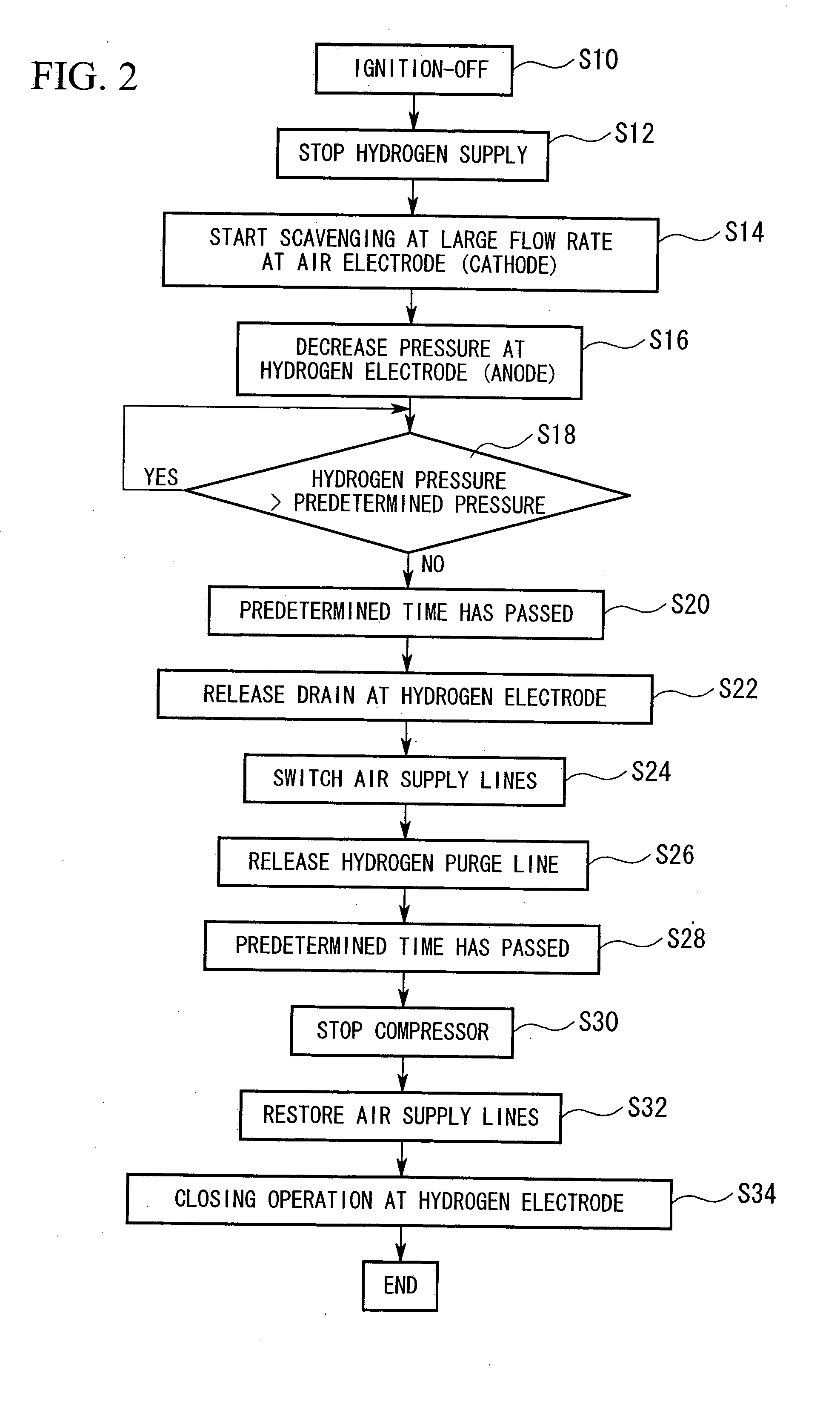
[0026] Embodiments of a stop method for a fuel cell system according to the invention will be explained below with reference to the appended drawings. The embodiment to be explained below is an example of a stop method for a fuel cell system that is to be installed in a fuel cell powered vehicle.

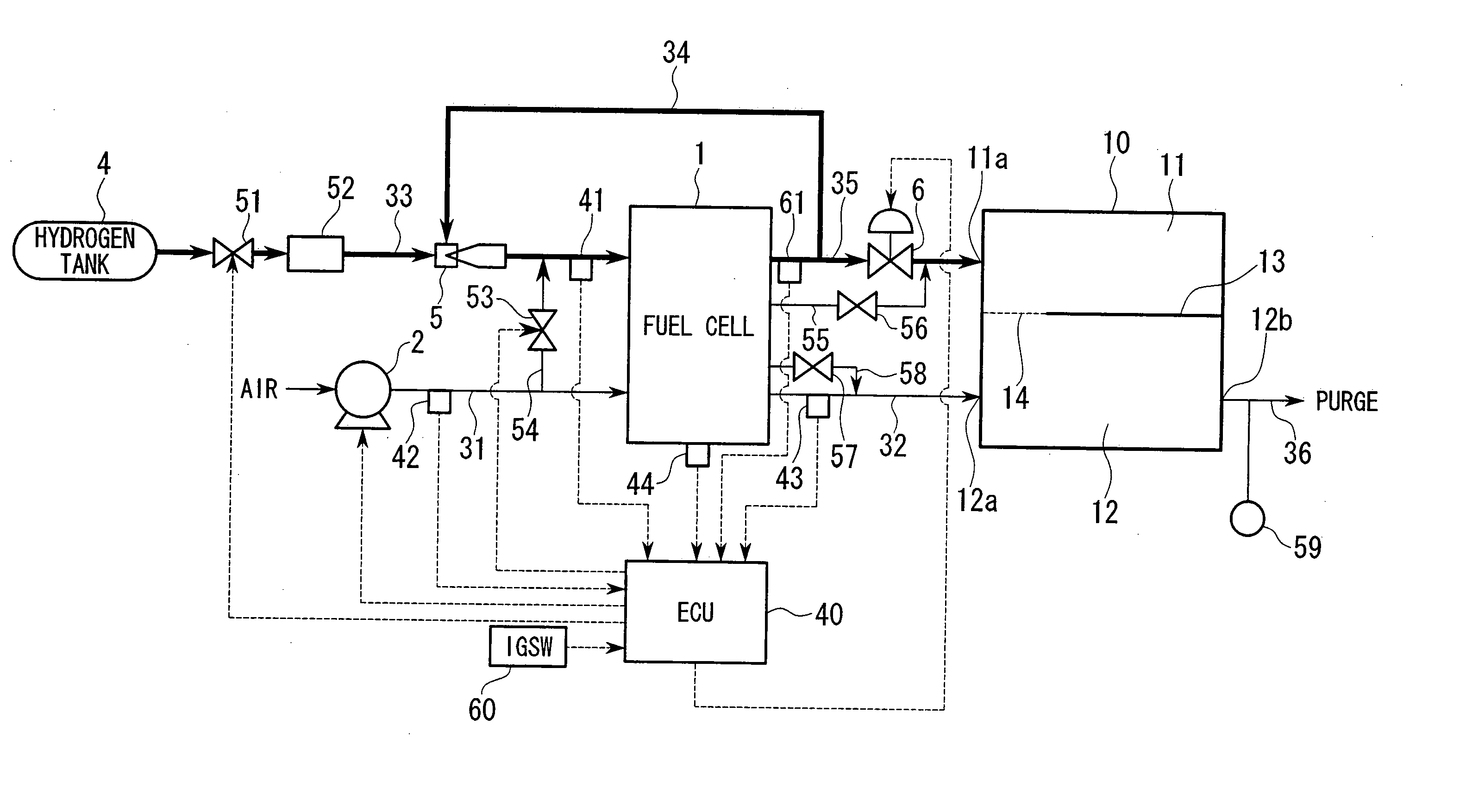
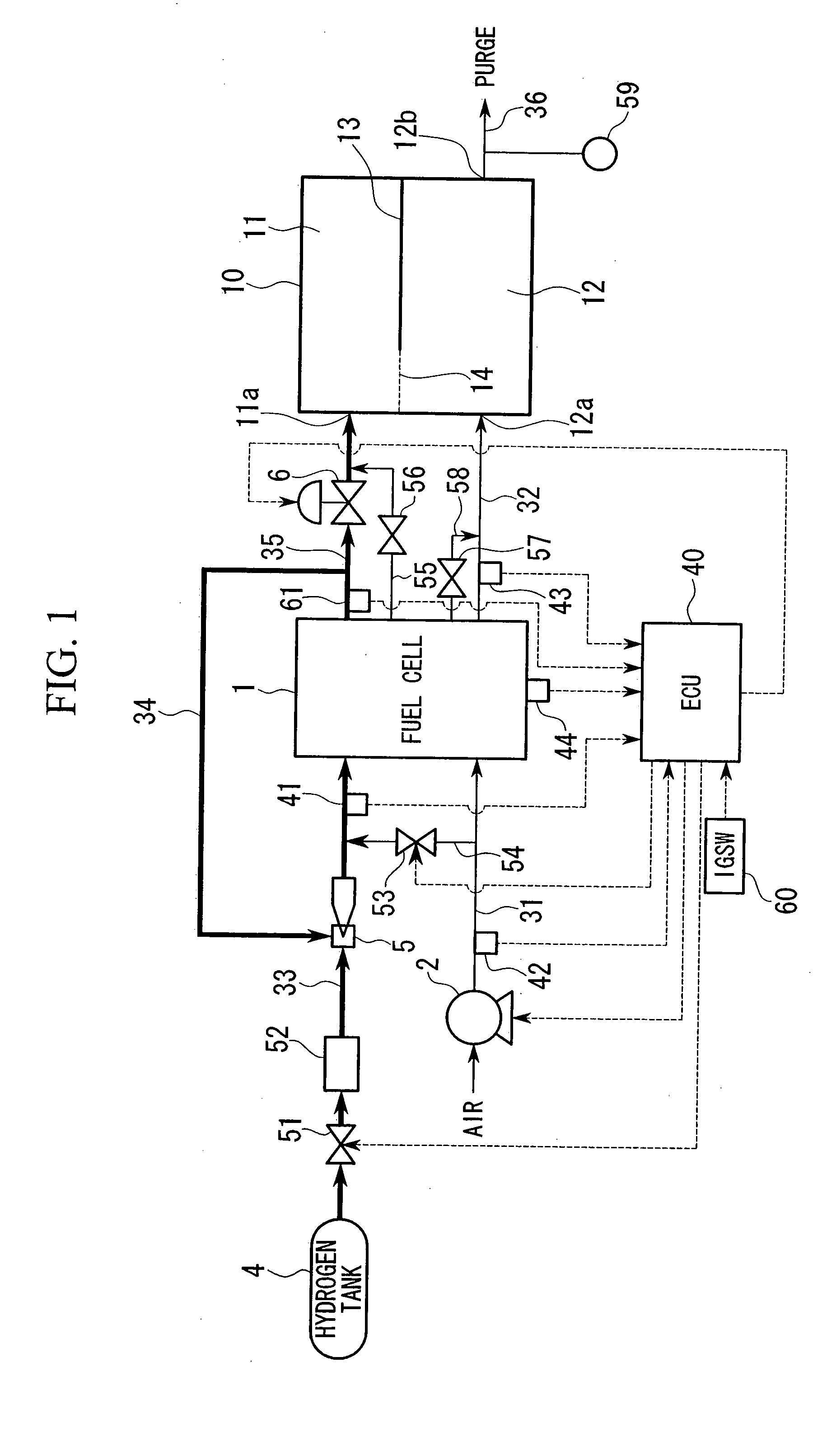
[0027]FIG. 1 is a schematic block diagram showing a fuel cell system to which a stop method for a fuel cell system according to a first embodiment of the present invention is applied.

[0028] A fuel cell 1 is a stack that is formed by stacking a plurality of fuel cell units, each of which includes a solid polymer electrolyte membrane consisting of, for example, a solid polymer ion exchange membrane, and an anode and a cathode that sandwich the solid polymer electrolyte membrane therebetween. When hydrogen as a fuel gas is supplied to the anode, and air containing oxygen as an oxidizing gas is supplied to the cathode, hydrogen ions are produced in the anode area by catalytic reaction, which p...


PUM


Abstract

A stop method for a fuel cell system that includes a fuel cell unit in which hydrogen is supplied to an anode, and air is supplied to a cathode so as to generate electrical power via an electrochemical reaction. The stop method includes the steps of stopping supply of hydrogen to the anode, and supplying air to the anode so as to discharge water remaining at the anode.

Description

BACKGROUND OF THE INVENTION [0001] 1. Field of the Invention [0002] The present invention relates to a stop method for a fuel cell system which is adapted for cold start-up. [0003] Priority is claimed on Japanese Patent Application No. 2003-347194, filed Oct. 6, 2003, the content of which is incorporated herein by reference. [0004] 2. Description of the Related Art [0005] In recent years, fuel cell powered vehicles have been proposed, each of which includes a fuel cell system as a driving source of the vehicle. As a type of fuel cell; system for such vehicles, a fuel cell system is known which includes a predetermined number of cell units stacked one on the other, each of which includes an anode, a cathode, and an electrolyte membrane sandwiched therebetween. When hydrogen is supplied to the anode and air (oxygen) is supplied to the cathode, electrical power generation is performed via an electrochemical reaction of hydrogen and oxygen which is accompanied by producing of water. Eve...

Claims


Application Information

Patent Timeline
IPC IPC(8): H01M8/00H01M8/04H01M8/10
CPCY02E60/50H01M8/04231
Inventor INAI, SHIGERUHAYASHI, KATSUMIJINBA, RYOKATO, HIDEOKOBAYASHI, TOMOKIUOSHIMA, MINORUKOTANI, YASUNORI
Owner HONDA MOTOR CO LTD
Why Eureka
Try Eureka