
Model and method for computing performance bounds in multi-hop wireless networks

a wireless network and performance bound technology, applied in the field of computer networks, can solve problems such as unrealistic assumption, and achieve the effects of improving traffic load, improving per-node throughput, and increasing opportunities for routing

Active Publication Date: 2005-04-07
ZHIGU HLDG
View PDF12 Cites 66 Cited by
  • Summary
  • Abstract
  • Description
  • Claims
  • Application Information

AI Technical Summary

Benefits of technology

The generality of the model and method is an additional advantage possessed by the present invention. This generality allows for accommodation of a diversity of wireless network characteristics such as the availability of multiple (non-overlapping) channels, multiple radios per node, and directional antennae. Furthermore, the model and method of the present invention can accommodate multiple MAC protocol models as well as single-path and multi-path routing constraints.
Finally the model and method of the present invention can be employed to evaluate how the per-node throughput in a multi-hop wireless network varies as the number of nodes grows. Previous work suggests that the per-node throughput falls as the number of nodes grows. But this result is under the assumption that nodes always have data to send and are ready to transmit as fast as their wireless connection will allow. In a realistic setting, however, sources tend to send data at a steady rate—which may be lower than the link capacity—so nodes will on average transmit at a slower rate than the speed of their wireless link. In such a setting, the model and method of the present invention finds that the addition of new nodes can actually improve the per-node throughput because the richer connectivity (and hence increased opportunities for routing around interference “hotspots” in the network) more than offsets the increase in traffic load caused by the new node.

Problems solved by technology

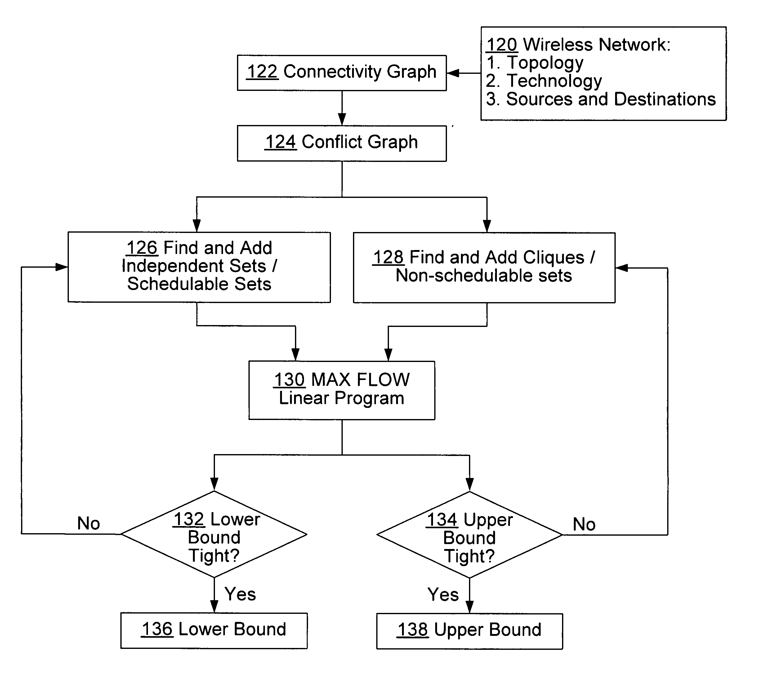
However, this problem turns out to be NP-hard, so instead methods for computing upper and lower bounds on the optimal throughput are disclosed.
While this assumption may be unrealistic, it gives a best case bound against which to compare practical algorithms for routing, medium access control, and packet scheduling.

Method used


Image

  • Model and method for computing performance bounds in multi-hop wireless networks
  • Model and method for computing performance bounds in multi-hop wireless networks
  • Model and method for computing performance bounds in multi-hop wireless networks

Examples


Embodiment Construction

In the description that follows, the invention is described with reference to acts and symbolic representations of operations that are performed by one or more computers, unless indicated otherwise. As such, it will be understood that such acts and operations, which are at times referred to as being computer-executed, include the manipulation by the processing unit of the computer of electrical signals representing data in a structured form. This manipulation transforms the data or maintains them at locations in the memory system of the computer, which reconfigures or otherwise alters the operation of the computer in a manner well understood by those skilled in the art. The data structures where data are maintained are physical locations of the memory that have particular properties defined by the format of the data. However, while the invention is being described in the foregoing context, it is not meant to be limiting as those of skill in the art will appreciate that several of t...


PUM


Abstract

Disclosed is a general model and method for computing performance bounds in multi-hop wireless networks. Rather than focusing on computing asymptotic performance bounds under assumptions of homogeneity or randomness in the network topology and / or workload, the present invention accommodates any given network, technology, interference model, routing paradigm, and workload. Using a conflict graph to formally characterize the impact of wireless interference on the performance of multi-hop wireless networks, methods for computing upper and lower bounds on the capacity of a given wireless network are detailed. Besides computing network capacity, the model and method disclosed can also enable or benefit other applications including maximizing fairness and minimizing maximum link utilization.

Description

TECHNICAL FIELD The present invention relates generally to computer networks and, more particularly, to computing performance bounds in multi-hop wireless networks. BACKGROUND OF THE INVENTION Multi-hop wireless networks have been the subject of much study over the past few decades. Much of the original work was motivated by military applications such as battlefield communications. More recently, however, some interesting commercial applications have emerged. One example is “community wireless networks”, where a multi-hop wireless network, perhaps based on the IEEE 802.11 standard, is used to provide the “last-mile” to peoples' homes. A very different example is sensor networks where the scale and environment make a multi-hop wireless network the only feasible means of communication. A fundamental issue in multi-hop wireless networks is that performance degrades sharply as the number of hops traversed increases. As a simple example, in a network comprising nodes with identical an...

Claims


Application Information

Patent Timeline
IPC IPC(8): H04L12/28H04L12/56H04W16/14
CPCH04W16/14
Inventor JAIN, KAMALPADHYE, JITENDRA D.PADMANABHAN, VENKATA N.QIU, LILI
Owner ZHIGU HLDG
Learn More