Mixed deposit friction material

a friction material and mix technology, applied in friction clutches, synthetic resin layered products, tyre parts, etc., can solve the problems of not being suitable for high-energy applications, and achieve the effect of durable friction material and high-performance us

Inactive Publication Date: 2005-04-07
BORGWARNER INC
View PDF28 Cites 38 Cited by
  • Summary
  • Abstract
  • Description
  • Claims
  • Application Information

AI Technical Summary

Benefits of technology

[0023] The present invention is especially useful with a primary layer comprising a fibrous base material comprising aramid fibers alone and / or combinations of less fibrillated aramid fibers, cotton fibers, carbon fibers, carbon particles and at least one filler material and, optionally, other ingredients. In certain examples, the less fibrillated aramid fibers create a porous fibrous base material. The carbon fibers provide the friction material with good heat conduction such that the friction material has desired heat resistance. The carbon particles also provide the friction material with good friction characteristics such as a good or smooth “feel” in shift and essentially noise or “squawk” free operation of the brakes and clutches. The presence of a small relative amount of cotton fibers provides the friction material with desired “break-in” characteristics such that there is little or no shudder occurring during the initial use of the friction material.
[0026] The mixture of carbonaceous material and friction modifying material provide the friction material with good heat conduction such that the friction material has desired heat resistance. The carbonaceous material in the mixture also provide the friction material with good friction characteristics such as a good or smooth “feel” in shift and essentially noise or “squawk” free operation of the brakes and clutches. In certain embodiments, the presence of a small relative amount of cotton fibers provides the friction material with desired “break-in” characteristics such that there is little or no shudder occurring during the initial use of the friction material.
[0028] The friction material of the present invention has improved “hot spot” resistance, desirable friction characteristics for “smooth shifts”, high heat resistance durability, elasticity, improved strength and porosity.
[0033] The fibrous base material can be impregnated using different resin systems. In certain embodiments, it is useful to impregnate the fibrous based material with a phenolic resin or a modified phenolic-based resin. In certain embodiments, when a silicone resin is blended or mixed with a phenolic resin in compatible solvents and that silicone-phenolic resin blend is used to impregnate a fibrous base material of the present invention, an especially useful high performance, durable friction material is formed.

Problems solved by technology

Both commercially available brake linings and transmission materials were investigated and proved not to be suitable for use in high-energy applications.

Method used


Image

  • Mixed deposit friction material
  • Mixed deposit friction material
  • Mixed deposit friction material

Examples


examples

[0096] Slip Clutch Interface Technology Requirements: The friction materials of the present invention are designed for slipping clutch applications that meet special requirements. These requirements include high mechanical strength, heat resistance, durability, stability, and shudder resistance. The friction material of the present invention has high porosity, a unique material structure for high mechanical strength, high temperature conductivity, and anti-shudder friction modifier characteristics. These material characteristics are the necessary conditions of smooth slip torque output and long term friction stability.

[0097] The slip clutch material requirements for desirable slip torque response and long-term durability include good curve shape and long term friction stability. The good curve shape is dependent on high material porosity and high friction modifier content. The long term friction stability is dependent on high porosity (anti-glazing) and high temperature ingredients...

example i

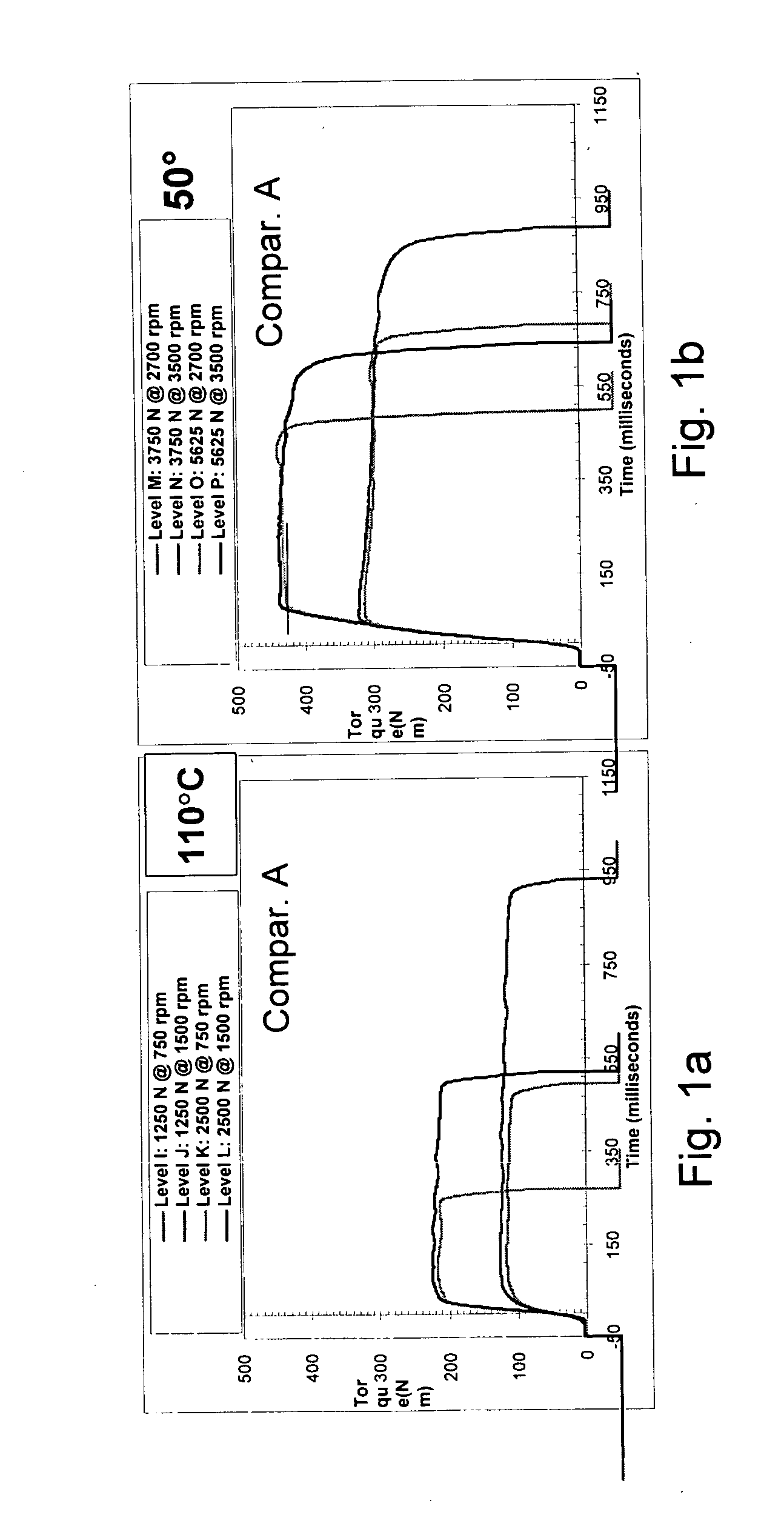
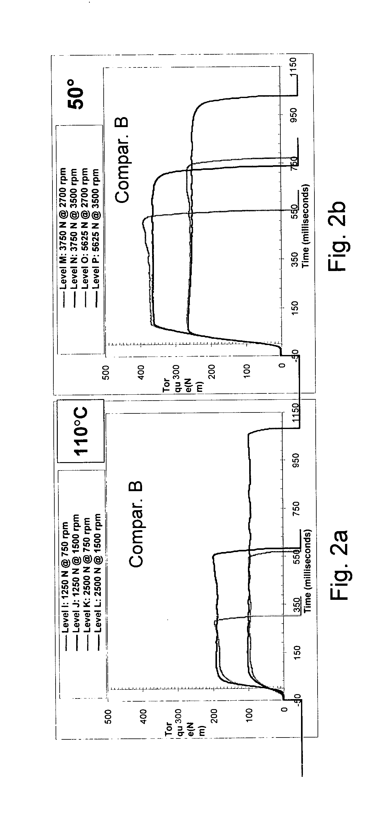
[0100] The torque curve shape indicates that the friction material of the present invention is especially useful in speed, high energy and high temperature application. The stable torque curve also shows that the friction material is noise free.

[0101] Table 1 shows the formulations for comparative examples A and B, and Examples 1 and 2. Table I also shows the basis weight, caliper, porosity, dry and wet tensile and ash properties for the examples shown. The new materials comprise a primary layer having an optimal amount of carbon fiber and a secondary layer comprises a mixture of carbon and celite and, optionally, a retention aid such as latex. In the secondary layer, in preferred embodiments, the ratio of carbon particles to silica ranges from about 1 to 4 to about 1 to 2.

TABLE ICompar.Compar.Furnish %Example 1Example 2Example AExample BPrimary LayerAramid fiber555520-2540-60Carbon 9 μm151510-20Cotton25-35Graphite252515-2510-20Silica5520-3015-25Latex22WSRX2X2Secondary LayerCarbo...

example ii

[0102] The μPVT torque curves provide further information about the materials of the present invention.

[0103]FIGS. 1a and 1b the torque curves (μPVT) for Comparative example A at various levels and speed at 110° C. (FIG. 1a) and at 50° C. (FIG. 1b).

[0104]FIGS. 2a and 2b the torque curves (μPVT) for Comparative example B at various levels and speed at 110° C. (FIG. 2a) and at 50° C. (FIG. 2b).

[0105]FIGS. 3a and 3b the torque curves (μPVT) for Example 1 at various levels and speed at 110° C. (FIG. 3a) and at 50° C. (FIG. 3b).

[0106]FIGS. 4a and 4b the torque curves (μPVT) for Example 2 at various levels and speed at 110° C. (FIG. 4a) and at 50° C. (FIG. 4b).


PUM

PropertyMeasurementUnit
sizeaaaaaaaaaa
lengthaaaaaaaaaa
sizeaaaaaaaaaa

Abstract

The present invention relates to a friction material having a fibrous base material as a primary layer and a secondary layer comprising a mixture of carbonaceous material and friction modifying particles on at least one surface of the primary layer for use as an anti-shudder friction material.

Description

BACKGROUND ART [0001] New and advanced transmission systems and braking systems are being developed by the automotive industry. These new systems often involve high-energy requirements. Therefore, the friction materials technology must be also developed to meet the increasing energy requirements of these advanced systems. [0002] In particular, a new high performance, durable friction material is needed. The new friction material must be able to withstand high speeds wherein surface speeds are up to about 65 m / seconds. Also, the friction material must be able to withstand high facing lining pressures up to about 1500 psi. It is also important that the friction material be useful under limited lubrication conditions. [0003] The friction material must be durable and have high heat resistance in order to be useful in the advanced transmission and braking systems. Not only must the friction material remain stable at high temperatures, it must also be able to rapidly dissipate the high he...

Claims


Application Information

Patent Timeline
Patent Type & Authority Applications(United States)
IPC IPC(8): F16D13/62C04B35/83C08J5/14C09K3/14F16D69/00F16D69/02
CPCF16D69/023F16D2069/008F16D69/026F16D2200/0091Y10T428/24994Y10T428/249952F16D69/02
Inventor LAM, ROBERT C.
Owner BORGWARNER INC
Why Eureka
Try Eureka