Medical device supporting apparatus

a technology for supporting devices and medical devices, applied in medical science, surgery, diagnostics, etc., can solve problems such as power cable disconnections and brake control system failures

Inactive Publication Date: 2005-04-07
OLYMPUS CORP
View PDF14 Cites 52 Cited by
  • Summary
  • Abstract
  • Description
  • Claims
  • Application Information

AI Technical Summary

Benefits of technology

[0010] In this arrangement, at least two final control elements being different in the amount of operating force, is turned OFF sequentially from the one having a larger operating force when the amount of operating force is reduced for releasing the operation. Therefore, the user (the operator) can recognize completion of operation of two final control elements reliably. Therefore, locking and unlocking operation of the medial treatment device with high degree of reliability and accuracy can be realized simply and easily.
[0012] When controlling the state of the holding members as described above, the operation of the operating member having the largest operating force is released first when the user weakens the force for releasing the operation of the operating member. In other words, the operating member which is released first is fixed, and hence when the operation of this specific operating member is released, the holding device is restored to the locked state. Therefore, the restoring operation from the moving state to the locked state is stabilized and is performed quickly.
[0014] In this arrangement, the medical device locked in position and supported by the supporting mechanism can adjust the movement of the joints by adjusting the force for locking the joints without performing the locking and unlocking operation of the joints of the supporting mechanism. Therefore, even in the case in which the locking state of the joints can hardly be released by the control unit, the supporting mechanism can be moved by weakening the locking force, so that the movement of the medical device including retraction is enabled.

Problems solved by technology

Therefore, there is a risk that somebody steps on the power cable when moving the apparatus including such equipment, which may result in disconnection of the power cable or failure of the brake control system.

Method used


Image

  • Medical device supporting apparatus
  • Medical device supporting apparatus
  • Medical device supporting apparatus

Examples


first embodiment

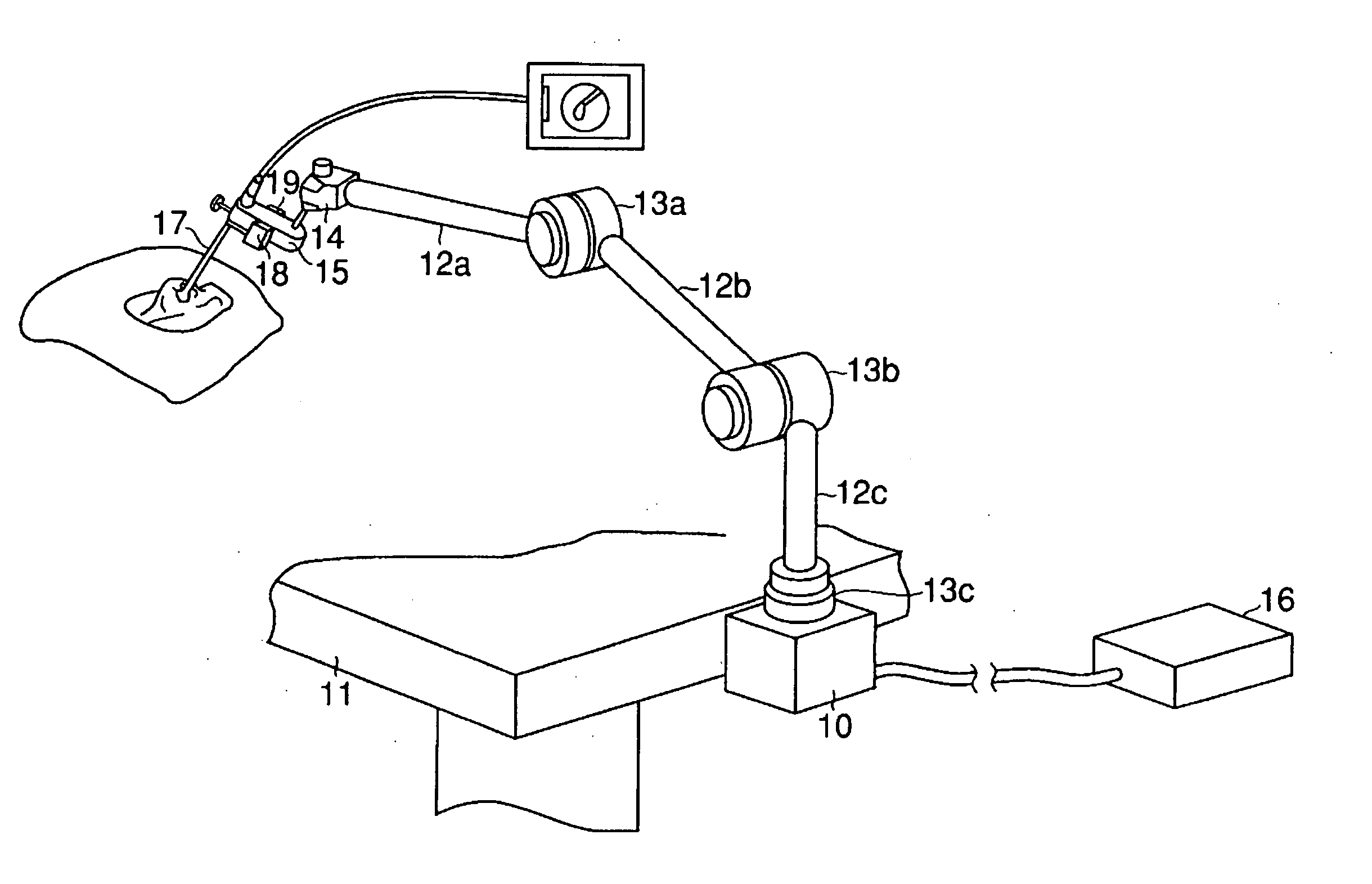
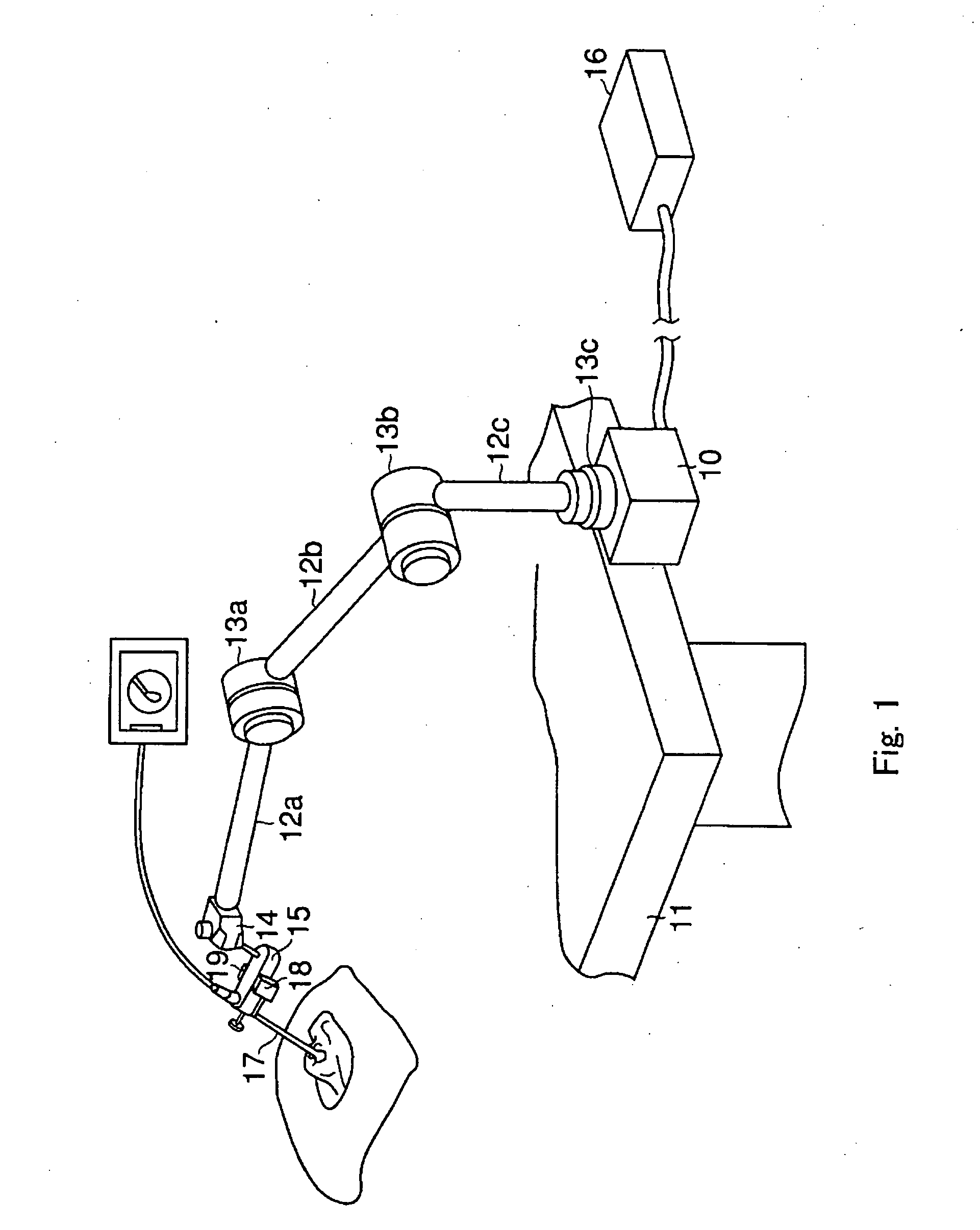
[0032]FIG. 1 shows a medical device supporting apparatus according to the present invention. A supporting base 10 is detachably attached to a mounting body 11 such as a floor or a bed. Arms 12a, 12b, 12c are joined to the supporting base 10 via joints 13a, 13b, 13c in sequence. A holding device 15 for mounting a medical device is attached to the distal arm 12a via a ball joint 14. The ball joint 14 can include an electromagnet (not shown), which has an electromagnetic brake built therein. The electromagnet (not shown) is electrically connected to a control box 16 which constitutes a control unit, and is driven under the control of the control box 16. In other words, the electromagnet (not shown) performs locking and unlocking of the position of the ball joint 14 according to presence or absence of electric distribution.

[0033] As a medical device for giving treatment or observing a patient, for example, an endoscope 17 is inserted into and supported by the holding device 15. The hold...

second embodiment

[0052] the present invention will now be described.

[0053]FIG. 4 and FIG. 5 show a medical device supporting apparatus according to the second embodiment of the invention, and include an emergency operating device in addition to the aforementioned first embodiment, which is expected to have the same effect as the first embodiment. Therefore, in FIG. 4 and FIG. 5, identical parts to FIGS. 1 to 3 are represented by the identical numerals and detailed description will not be made.

[0054] In other words, for example, the endoscope 17 is detachably inserted into the holding device 15. At the position of the holding device 15 in the vicinity of the endoscope mounting position, there are provided recessed first and second switch storage portions 151, 152 so as to oppose each other, and first and second micro switches 40, 41 are stored and disposed in the first and second switch storage portions 151, 152 so as to be operated in the opposite direction. The first and second micro switches 40, ...

third embodiment

[0065] Subsequently, the present invention will be described.

[0066]FIG. 7 shows a medical device supporting apparatus according to the third embodiment of the present invention, which is expected to have the same effect as the first and second embodiments. Therefore, in FIG. 7, identical parts to FIG. 1 are represented by the identical numerals and detailed description will not be made.

[0067] In other words, the aforementioned arms 12a, 12b, 12c are connected via a joint 60a, a joint 60b, and joint 60c, in which known fluid (pneumatic pressure) brakes are integrated, in sequence. The fluid brake is adapted to release the locking state of the brake when a pressure is applied. The holding device 15 is movable connected to the arm 12a via a ball joint 61 in which a fluid (pneumatic pressure) brake is integrated in the same manner. These fluid brakes are connected to a pneumatic pressure control device, described later, which is integrated in a carrier base 62 for supporting the arms 1...


PUM


Abstract

A medical device supporting apparatus for supporting a medical device in a three-dimensional space, in which a holding device for holding the medical device is supported by a supporting mechanism three-dimensionally, and the state of the supporting unit is switched between the movable state and the locked state by operating a plurality of final control elements. Operation is stabilized by differentiating the amount of operating force of the plurality of final control elements.

Description

CROSS-REFERENCE TO RELATED APPLICATION [0001] This application is based upon and claims the benefit of priority from prior Japanese Patent Application Nos. 2003-345995, filed on Oct. 3, 2003 and 2004-036663, filed on Feb. 13, 2004, the entire contents of each of which are incorporated herein by reference. BACKGROUND OF THE INVENTION [0002] 1. Field of the Invention [0003] The present invention relates to a medical device supporting apparatus used for positioning a medical device at an operative portion. For example, a medical device supporting apparatus of the invention is used for positioning an endoscope with respect to the operative portion in a surgical operation during a cranial nerve surgery. [0004] 2. Description of the Related Art [0005] Generally, there is a medical device supporting apparatus for supporting a medical device disclosed in JP-A-2002-345831. The medical device supporting apparatus includes a plurality of arms connected via joints provided with brakes for locki...

Claims


Application Information

Patent Timeline
Patent Type & Authority Applications(United States)
IPC IPC(8): A61B1/00A61B17/00A61B19/00
CPCA61B19/26A61B2019/266A61B2017/00544A61B2017/00539A61B90/50A61B2090/508A61B1/00149
Inventor OTSUKA, SATOSHISHINMURA, TORUYAMASHITA, TOMOAKI
Owner OLYMPUS CORP
Why Eureka
Try Eureka