Shear reducing chair cushion

a chair cushion and shear-reducing technology, applied in the field of chair cushions, can solve the problems of reduced skin integrity, reduced circulation, impaired nutrition, etc., and achieve the effects of reducing shear stress on the body, uniform thickness, and optimally receiving different portions

Active Publication Date: 2005-04-14
SPAN-AMERICA MEDICAL SYSTEMS
View PDF3 Cites 13 Cited by
  • Summary
  • Abstract
  • Description
  • Claims
  • Application Information

AI Technical Summary

Benefits of technology

[0010] The present invention may comprise a support surface for which the uppermost portions of the support ribs reside in a single plane—that is to say, the cushion may have a uniform thickness. Alternatively, the cushion may have different thicknesses at different locations, adapted to more optimally receive different portions of a person's body situated thereon and to thereby minimize shear stress to the person's body. In one embodiment, the portion of the support surface adapted for receipt of the head and upper torso may define a progressively increasing thickness from the head area to the back area, with the maximum of such increasing thickness achieved at the lumbar area; the portion adapted for receipt of the gluteal region may comprise a first

Problems solved by technology

Also known as “bed sores” and “pressure ulcers,” decubitus ulcers may result in part from physiological causes such as decreased circulation, reduced skin integrity, impaired nutrition, and other bodily weaknesses.
Of course, a generally planar surface, supporting the very non-planar human body, will result in even smaller areas of support, with concomitant greater increase in the pressure upon those areas.
As a person sits in a chair, for example, perspiration from skin in contact with the chair cushion surface may tend to accumula

Method used


Image

  • Shear reducing chair cushion
  • Shear reducing chair cushion
  • Shear reducing chair cushion

Examples


Embodiment Construction

[0023] Reference will now be made in detail to the presently preferred embodiments to the invention, one or more examples of which are illustrated in the drawings. Each example is provided by way of explanation of the invention, and not meant as a limitation of the invention. For example, features illustrated or described as part of one embodiment may be used on another embodiment to yield a still further embodiment. It is intended that the present application includes such modifications and variations as come within the scope and spirit of the invention. The same numerals are used to refer to the same features throughout the drawings and in the text that follows.

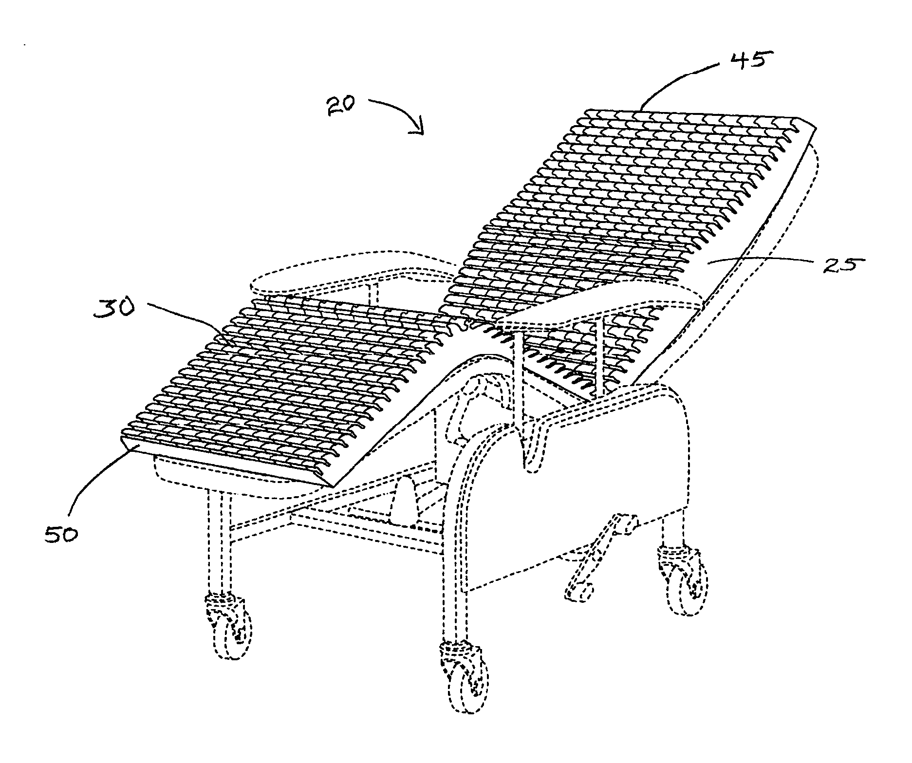
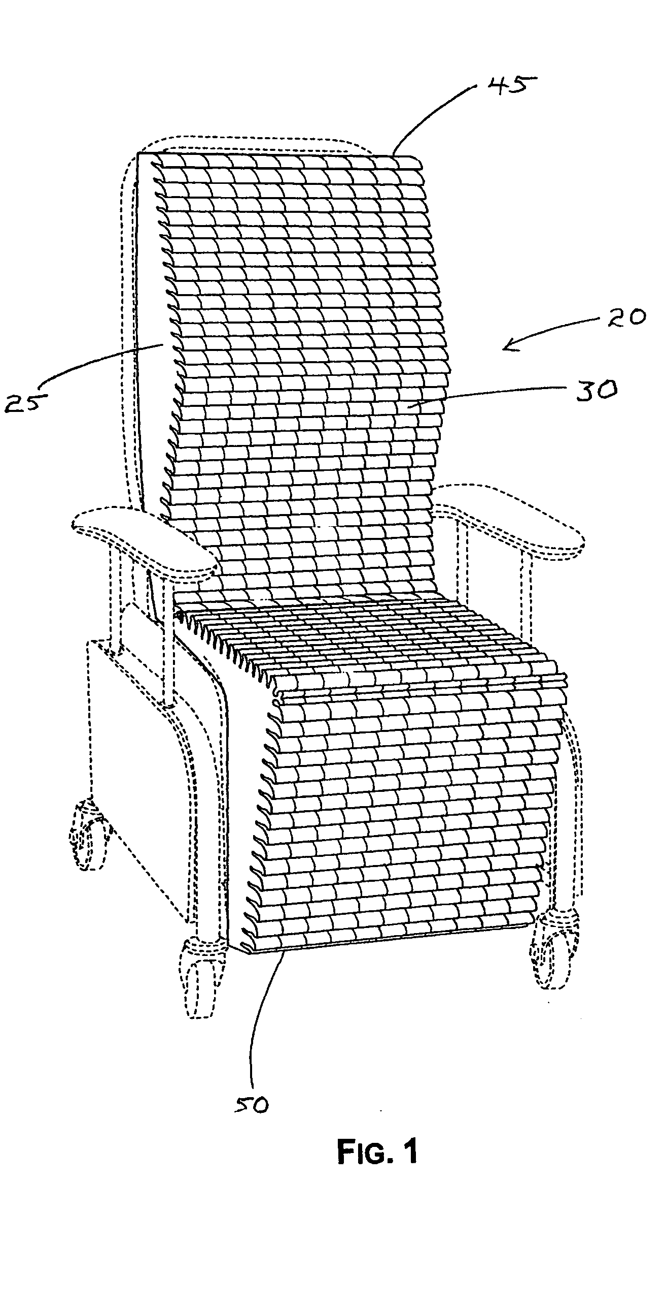
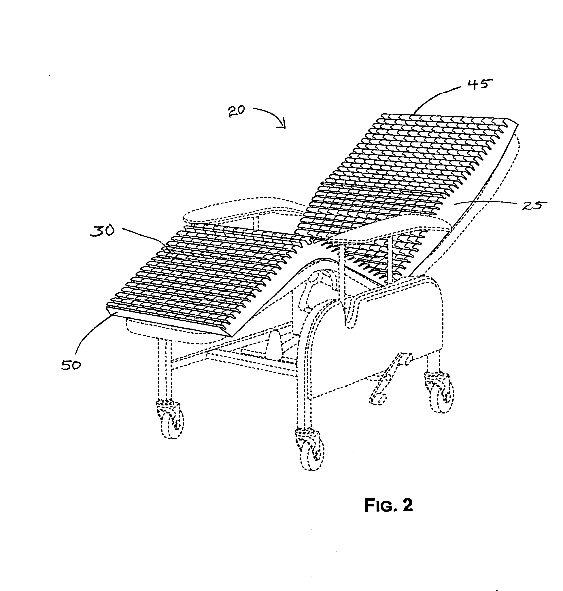
[0024] Referring to the Figures, a chair cushion generally 20 includes a main body 25 comprised of a resilient material, for example polyurethane foam. The chair cushion 20 is generally rectangular. As described herein, a “chair cushion” may be understood to be of any predetermined thickness; in the appended drawings, a th...


PUM

PropertyMeasurementUnit
Lengthaaaaaaaaaa
Distanceaaaaaaaaaa
Shear stressaaaaaaaaaa

Abstract

A foam chair cushion having transverse support ribs is provided for reduction of shear stress between a person's skin and the surface of the chair cushion. The chair cushion may include transverse, lateral support ribs upon the support surface of the cushion. The support ribs have a predetermined cross-sectional geometry that is curvilinear, with a superior aspect generally disposed for receipt of a person and a inferior aspect opposite. The inferior aspect of the cross-section of the support ribs may undercut the portion of the support ribs vertically above it. Having such cross-sectional geometry, the support ribs are directionally oriented, either toward the one end or the other of the chair cushion. The chair cushion may include support ribs that are directionally oriented toward the foot of the chair in regions adapted for the person's upper torso, buttocks, and lower legs, and directionally oriented toward the head of the chair in a region adapted for the person's thighs. The chair cushion may also include longitudinal cuts in the support surface, perpendicular to the transverse support ribs, thereby defining independent support cells upon the support surface.

Description

CROSS-REFERENCE TO RELATED APPLICATIONS [0001] This application claims benefit of U.S. Provisional Application No. 60 / 509,691, filed Oct. 8, 2003.BACKGROUND OF THE INVENTION [0002] This invention concerns a chair cushion with support surface features for reducing shear stress to the skin of a person received thereon. [0003] In medical care, the prevention of decubitus ulcers to the skin of non-ambulatory persons remains a goal. Also known as “bed sores” and “pressure ulcers,” decubitus ulcers may result in part from physiological causes such as decreased circulation, reduced skin integrity, impaired nutrition, and other bodily weaknesses. Certain areas of the body have been observed to have a relatively greater tendency to develop decubitus ulcers, including the spine, hips, buttocks, elbows, and heels. Conversely, certain portions of the body have been observed to have a relatively lesser tendency for the development of decubitus ulcers, such as the thigh area in which greater bloo...

Claims


Application Information

Patent Timeline
IPC IPC(8): A47C5/12A47C7/02A47C7/18A47C27/00A47C27/14
CPCA47C5/125A47C27/148A47C27/146
Inventor O'REAGAN, JAMES RICHARD
Owner SPAN-AMERICA MEDICAL SYSTEMS
Why Eureka
Try Eureka