Resistive touch screen incorporating conductive polymer

a technology of resistive touch screen and conductive polymer, which is applied in the direction of chemical indicators, instruments, chemical methods analysis, etc., can solve the problems of tao and zno not being as widely available on polyethylene terephthalate sheets, the discontinuity of film and film durability may arise, and the inability to achieve the same optical efficiency of the same sheet resistan

Inactive Publication Date: 2005-04-14
3M INNOVATIVE PROPERTIES CO
View PDF7 Cites 82 Cited by
  • Summary
  • Abstract
  • Description
  • Claims
  • Application Information

AI Technical Summary

Benefits of technology

In another aspect the present invention provides a resistive touch screen in which at least one of the two facing resistive layers is a conductive polymer layer. Controller electronics are electronically coupled to the resistive layers, the controller electronics being configured to use signals generated when the first and second resistive layers make local contact under a touch to determine the position of the touch. The touch screen yields 100,000 or more touch inputs in the same location before failure of the device when the controller electronics are operated at about 3 to 5 volts.
In yet anot

Problems solved by technology

As the layer of ITO becomes thinner, problems with resistance uniformity, discontinuity of the film and durability of the film may arise.
However, these oxides are more expensive and are not as optically efficient for the same sheet resistance as ITO.
In addition, TAO and ZnO are not as widely available on sheets of

Method used


Image

  • Resistive touch screen incorporating conductive polymer
  • Resistive touch screen incorporating conductive polymer
  • Resistive touch screen incorporating conductive polymer

Examples


example 2

5-wire devices were made using conducting polymer as both conductive layers. This example demonstrates the improvement in durability obtained by using conducting polymer as both conductive layers.

The experiment described in Comparative Example 1 was repeated, except that the 5-wire devices were fabricated using EL1500 as both the substrate and top conductive layers. The electrodes, interconnects and linearization pattern were screen printed onto the EL1500 using a silver ink available from DuPont under the trade designation 5089. The silver ink was cured at 130° C. for 6 minutes. The sensors were linear and accurate when operated with the 3M Touch Systems, Inc. SMT3 controller. Each of seven 5-wire sensors constructed was tap tested in three positions. The lifetime of the sensors ranged from 128,000 taps to 766,000 taps.

example 3

4-wire touch sensors were made with conducting polymer as both conductive layers. This example demonstrates linear 4-wire sensors made with conducting polymer.

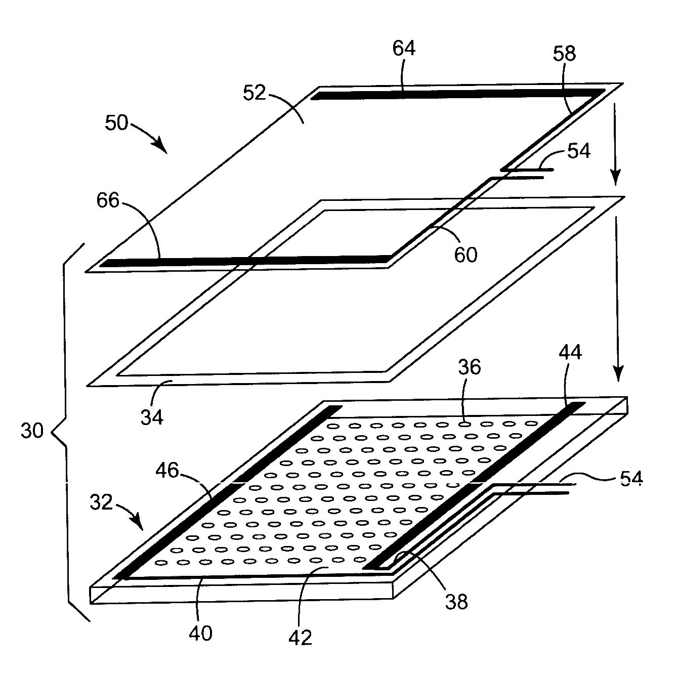
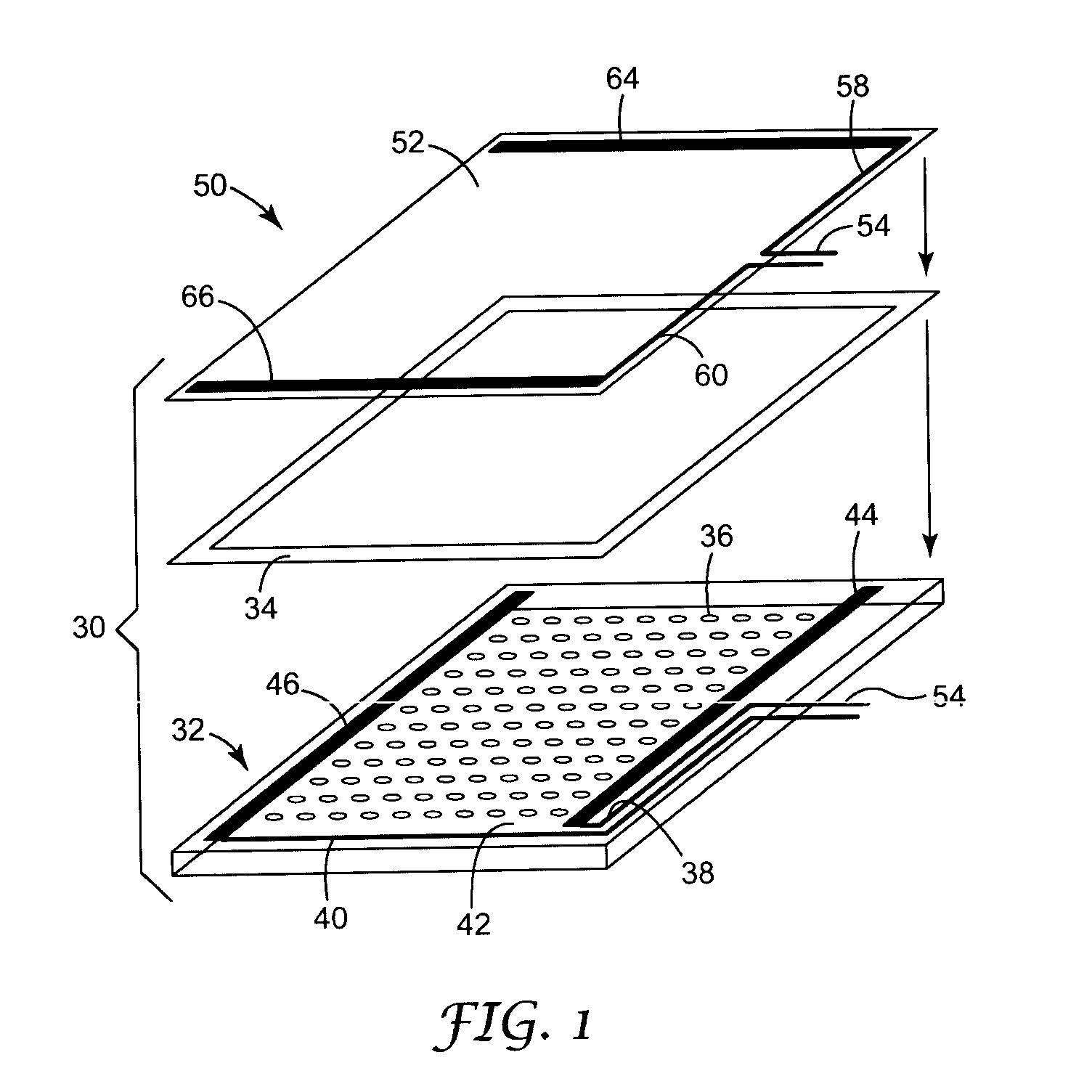
3 inch by 3 inch 4-wire touch sensors were fabricated by printing the DuPont 5089 silver ink onto EL1500 and curing as described in Example 2. Devices were assembled with the conductive sides facing but separated by a 0.003 inch thick frame of double sided tape positioned around the perimeter, which functioned as a spacer. A small piece of conductive tape available from Chromerics was attached to each of the four silver electrodes, and a wire was soldered onto each electrode using this tape and connected to the 3M Touch Systems, Inc. SC4 controller. The sensors functioned well, accurately detecting the location of touches and linear lines were drawn.

A stylus rub durability test was run on several sensors that were constructed according to this Example 3. A 0.8 mm radius PDA-type stylus weighted to apply 250 g was rubbed i...

example 4

Contrast ratio of PEDOT was compared to that of ITO. This example illustrates the optical advantages of conducting polymer compared to ITO.

Conducting polymer films having a range of sheet resistances were obtained from Agfa-Gavaert Corp. Contrast ratio, defined as total transmission divided by total reflectance, along with color shift of the films were compared to standard ITO. The PEDOT material, with much lower reflectance, gave a much higher contrast ratio than ITO. In addition, the PEDOT provided a blue color shift, which is much preferred for a display over the yellow shift given by ITO.


PUM


Abstract

Conductive polymers can be used as the signal carrying layers in resistive touch screens. Using conductive polymers can allow higher sheet resistance than is conventionally obtained using indium tin oxide while maintaining electrical continuity and durability of the layer. Higher sheet resistance can also lead to reduced errors and reduced power consumption, as well as better optical transmission. Sheet resistance may be limited on an upper end by desired data sampling rates. Also disclosed are resistive touch screens that employ a conductive polymer on both the topsheet and bottom substrate and that can be operated with the use of conventional electronics.

Description

FIELD OF THE INVENTION The present invention relates generally to touch sensors, particularly touch sensors that are used in conjunction with a display device to form a touch screen. BACKGROUND OF THE INVENTION Typical resistive touch screens include two clear conductive layers separated by spacers, the transparent conductive layers being formed of a transparent conductive oxide (TCO), commonly indium tin oxide (ITO), and sometimes tin antinomy oxide (TAO), tin oxide (TO) or zinc oxide (ZnO). Conventionally, resistive touch screens include opposing ITO layers with a surface resistivity, or sheet resistance, of about 250 to 600 ohms / square. ITO layers, and other TCOs, are generally vacuum deposited. Making an ITO layer with higher surface resistivity requires depositing a very thin layer. As the layer of ITO becomes thinner, problems with resistance uniformity, discontinuity of the film and durability of the film may arise. As a result, touch screen manufacturers typically use thic...

Claims


Application Information

Patent Timeline
IPC IPC(8): G06F3/033G06F3/045
CPCG06F3/045
Inventor CROSS, ELISA M.MOSHREFZADEH, ROBERT S.GEAGHAN, BERNARD O.
Owner 3M INNOVATIVE PROPERTIES CO
Why Eureka
Try Eureka