Transport line with grooved microchannels for two-phase heat dissipation on devices

Inactive Publication Date: 2005-04-14
WONG SHWIN CHUNG
View PDF10 Cites 46 Cited by
  • Summary
  • Abstract
  • Description
  • Claims
  • Application Information

AI Technical Summary

Benefits of technology

[0008] The object of this invention is to provide efficient flow of a coolant in a transport line for loop heat pipes, capillary pump loops or spray coolin

Problems solved by technology

More electronic function is invariably accompanied with temperature increase which may damage the chip.
In this method, a vaporization section vaporizes the coolant and carries away a large amount of heat energy, and the vapor fills the originally evacuated space.
This impedes the recycling capillary pumping action and tends to limit the maximum heat dissipation capability of the heat pipe.
The drawback of this structure is that the wicks in the condense

Method used


Image

  • Transport line with grooved microchannels for two-phase heat dissipation on devices
  • Transport line with grooved microchannels for two-phase heat dissipation on devices
  • Transport line with grooved microchannels for two-phase heat dissipation on devices

Examples


first embodiment

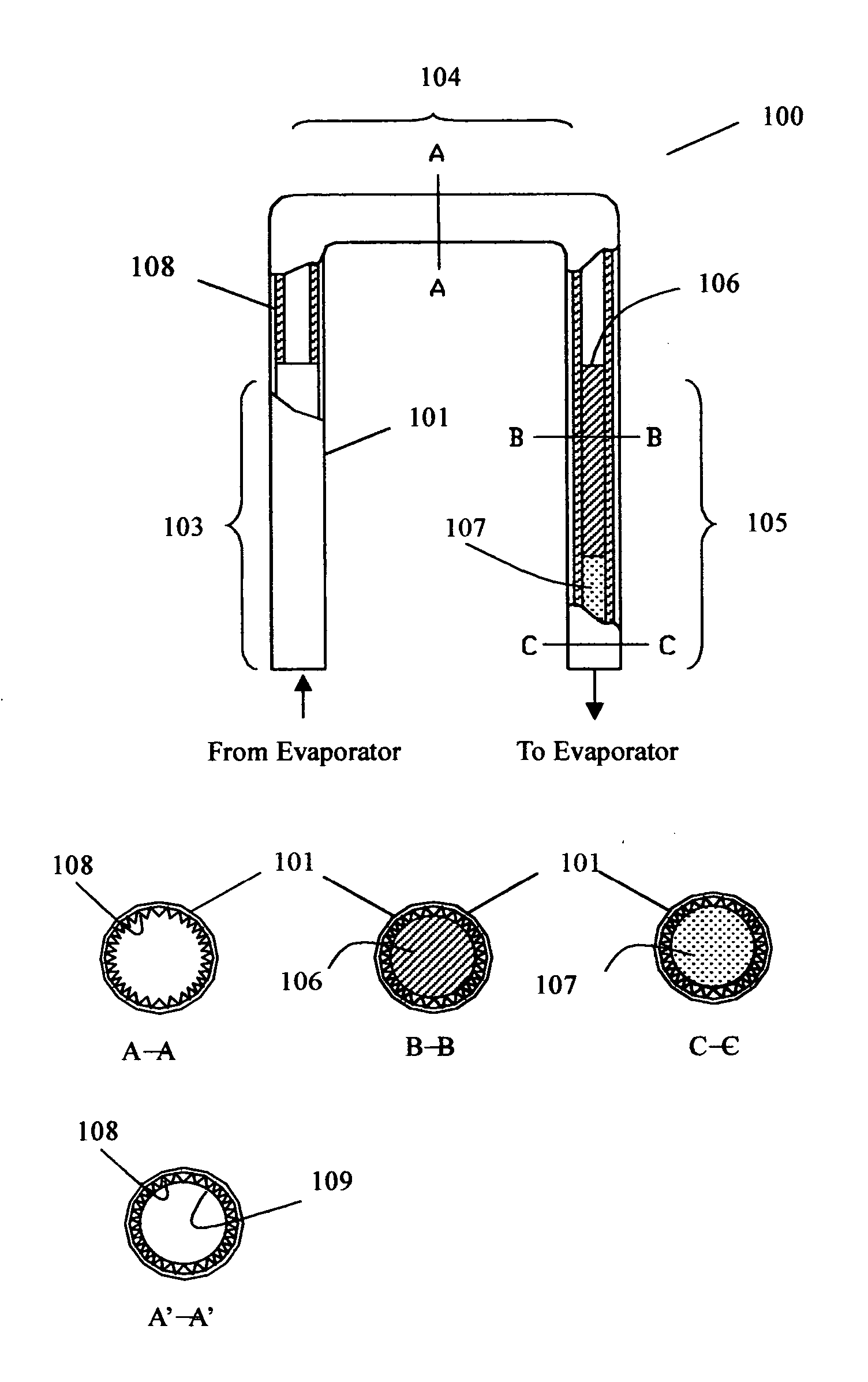
[0020]FIG. 3 shows the present invention. The flow path of the transport line 100 has sequential three sections: a vapor line 103, a condensation section 104, and a liquid line 105. The inner wall of the tubing 101 of the condensation section and liquid line is made with grooved microchannels 102, which can be made by extrusion molding during the fabrication of the tubing 101. The grooved microchannel has a hydraulic diameter smaller than the 500 μm. The cross-section of the groove can be triangular, rectangular, trapezoidal, wavy, or others. A plug 106 is inserted into the core of the liquid line 105 to reduce its effective cross-sectional area to only the groove microchannels, to enhance the pumping force. The plug 106 can be fabricated with metal, plastic or other heat resistant materials. The bottom corners of the grooved microchannels as shown in A-A section view help to collect the condensed liquid and convey it to the liquid line section. With the grooved microchannels closed...

second embodiment

[0023]FIG. 4 shows the present invention. This embodiment differs from the first embodiment in that a layer of wire mesh 109 is added to cover the grooved microchannels 102 for at least the condensation section 104, as shown in cross-section A-A, to improve the pumping ability. The material of the wire mesh can be metals or nonmetals.

third embodiment

[0024]FIG. 5 shows the present invention. The grooved microchannels are fabricated with a layer of a corrugated wire mesh to line in along the inner wall of the tubing 101 of the transport line. The vapor section 103 can be a tube only or inserted with a corrugated wire mesh as shown in the cross-section A-A, The condensation section 104 has a cross-section A-A with corrugated wire mesh lining 108. The liquid line section has a cross-section B-B with corrugated wire mesh enclosing a plug 106 which reduces the effective cross-sectional area for the liquid to flow. The wire mesh is corrugated with a cross-section shape either of triangular, rectangular, trapezoidal, wavy, or other groove shape with equivalent function. The corrugated wire mesh is basically inserted into the condensation section 104 and liquid line 105. A plug 106 is optionally inserted as a core in the liquid line 105 to reduce its effective cross-sectional area. An additional layer of wire mesh 109 can be optionally ...


PUM


Abstract

Grooved microchannels are used to enhance the capillary action in the transport line of two-phase heat dissipation devices, such as loop heat pipes, capillary pump loops, or spray cooling devices, or others. Efficient heat dissipations achieved by enhancing the capillary pumping force for the liquid flow without significantly increasing the friction force. The effective cross-sectional area of the liquid line is made smaller than that of the condensation section, either by inserting a plug or shrinking the liquid line, to provide additional pumping force for the coolant recycling.

Description

BACKGROUND OF THE INVENTION [0001] 1. Field of the Invention [0002] The invention related to two-phase heat dissipation devices, particularly to the transport line of loop heat pipes, capillary pump loops, spray cooling devices or others. The two-phase heat dissipation device is sued for heat removal of heat generating devices, such as the central processing unit (CPU) or other integrated circuit (IC) chips. [0003] 2. Brief Description of Related Art [0004] As electronic technology advances, more electronic function is performed in a smaller area on a semiconductor chip. More electronic function is invariably accompanied with temperature increase which may damage the chip. To maintain a safe temperature, it is necessary to remove the heat generated in the chip at the chip mount. [0005] A widely used method for cooling the chip mount is to utilize the two-phase heat transfer during phase transition between liquid phase and vapor phase of a coolant. In this method, a vaporization sect...

Claims


Application Information

Patent Timeline
IPC IPC(8): F28D15/04H01L23/427
CPCF28D15/043F28D15/046H01L23/427H01L2924/0002H01L2924/00
Inventor WONG, SHWIN-CHUNG
Owner WONG SHWIN CHUNG
Why Eureka
Try Eureka