Pressure container manufacturing method

Inactive Publication Date: 2005-04-14
SUBARU CORP
View PDF28 Cites 41 Cited by
  • Summary
  • Abstract
  • Description
  • Claims
  • Application Information

AI Technical Summary

Benefits of technology

[0009] The present invention is developed in view of the above described problems, and an object of the present invention is to provide a pressure container manufacturing meth

Problems solved by technology

Earlier, a pressure container made of metal which has high strength and is excellent in gas barrier property has been mainstream, however due to its heavy weight, there is a difficulty in applying it to a fuel tank of an automobile or a space plane in which weight saving is required.
However, applying the FW method or the TW method would raise a problem of requiring a long period of time to wind the tow shaped or tape shaped continuous prepreg on t

Method used


Image

  • Pressure container manufacturing method
  • Pressure container manufacturing method
  • Pressure container manufacturing method

Examples


first embodiment

[0044] The first embodiment of the present invention will be explained below referring to the drawings.

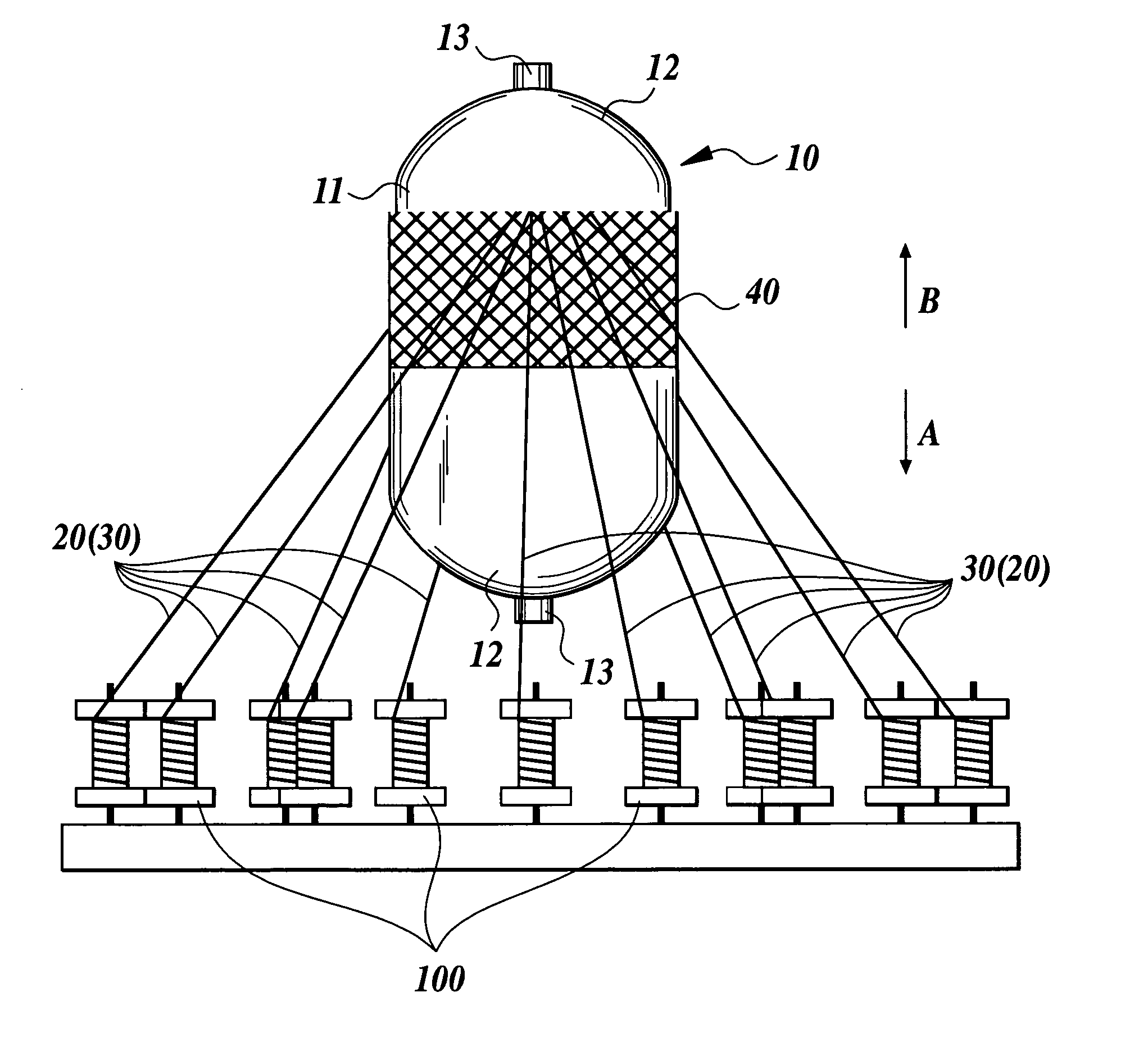
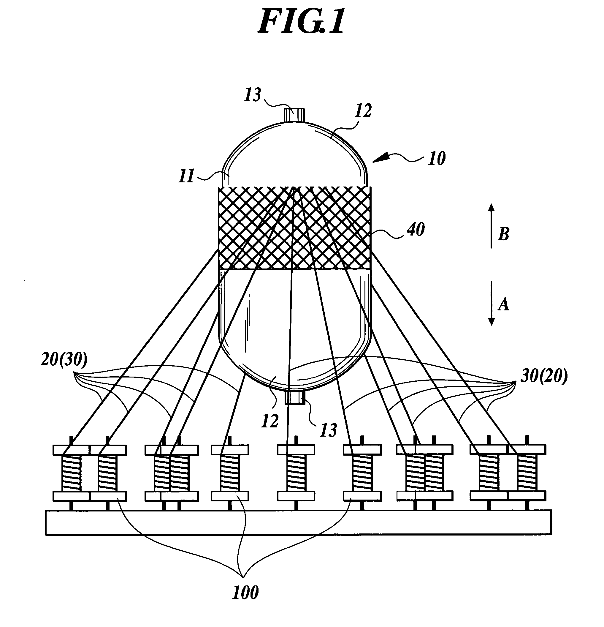
[0045] In this embodiment, the explanation will be made on a method to manufacture a CNG tank by forming an outer shell made of fiber reinforced composite material on the periphery of the liner 10 (refer to FIG. 1). The tank manufactured by the method according to this embodiment is a pressure container which can be filled with several hundred of atmospheres of CNG.

[0046] First, the liner 10 is molded by a material which is excellent in gas barrier property (liner molding step). In the embodiment, the liner 10 is molded by a blow molding method using liquid crystal resin which is excellent in dimensional stability and chemical resistance as well as gas barrier property. The liner 10, as shown in FIG. 1, comprises a cylindrical portion 11 and dome portions 12 formed at both ends of the cylindrical portion 11. A metal mouth piece 13 is attached to the top of each dome portion 12.

[...

second embodiment

[0063] The second embodiment of the present invention will be explained below referring to the drawings. The component that is same as in the first embodiment will be given the same reference numeral and the explanations thereof will be omitted. The tank manufactured by the manufacturing method according to this embodiment is a pressure container which can be filled with about 200 atmospheres of CNG.

[0064] First, the liner 10 is prepared with a material which is excellent in gas barrier property (liner preparing step).

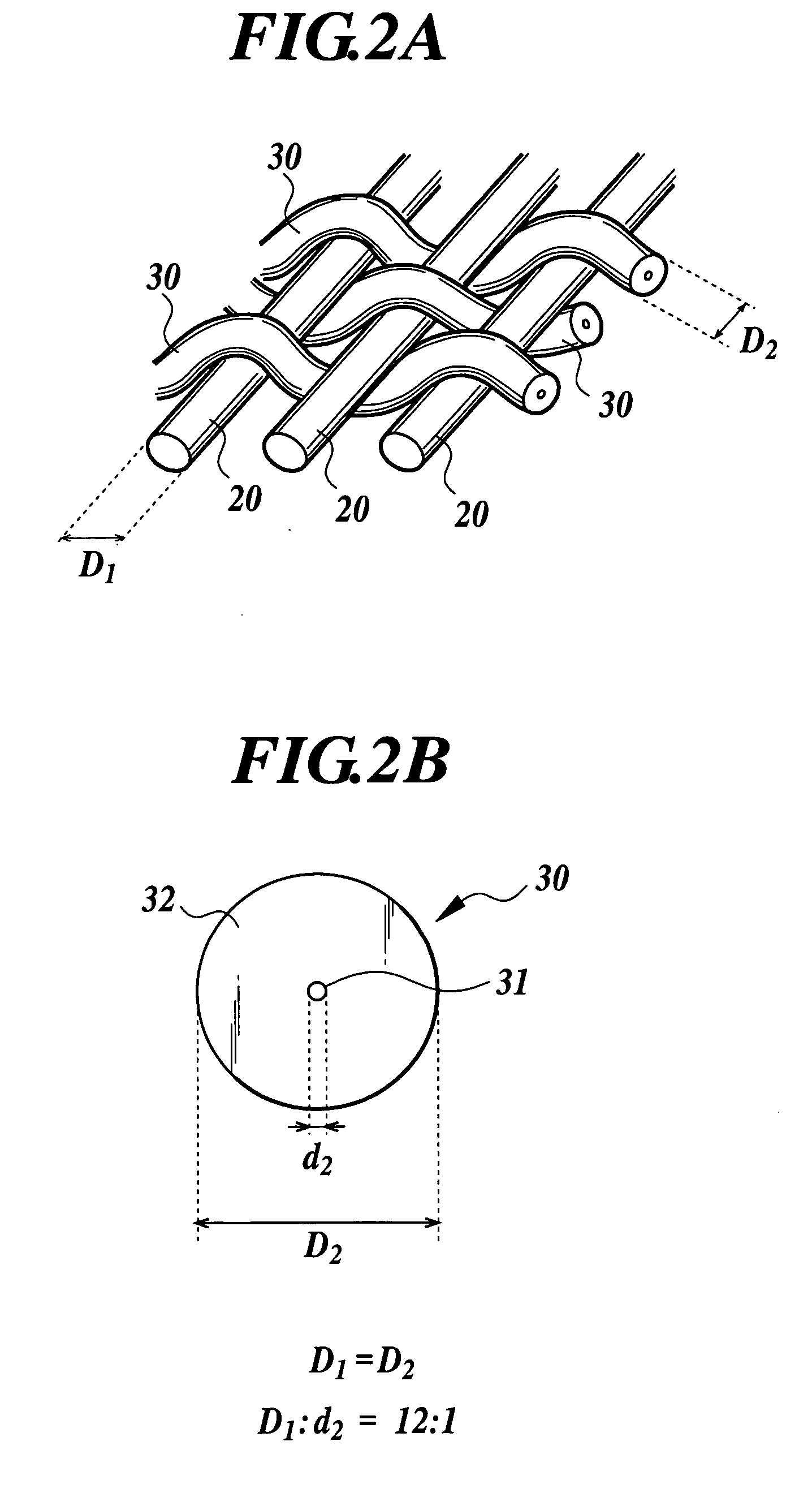
[0065] Next, first fiber bundles 120 each comprising a large diameter carbon fiber bundle (large diameter fiber bundle) and a second fiber bundle 130 comprising a small diameter carbon fiber bundle (small diameter fiber bundle) are prepared (fiber bundle preparing step).

[0066] In the embodiment, about 120,000 carbon fibers are bundled to prepare the first fiber bundle 120, and about 1,000 carbon fibers are bundled to prepare the second fiber bundle 130. The first fi...


PUM

PropertyMeasurementUnit
Angleaaaaaaaaaa
Angleaaaaaaaaaa
Angleaaaaaaaaaa

Abstract

A pressure container manufacturing method for manufacturing a pressure container by forming an outer shell made of a fiber reinforced composite material on a periphery of a liner, has: preparing a first fiber bundle which has a large diameter fiber bundle unimpregnated with a resin, and a second fiber bundle which has a small diameter resin bundle and a thermoplastic resin covering the small diameter resin bundle; forming a body on the periphery of the liner by braiding the first fiber bundle and the second fiber bundle with a braider; impregnating the first fiber bundle with the thermoplastic resin in the second fiber bundle which is heated and melted; and curing the thermoplastic resin to form the outer shell, wherein a tension applied to the first fiber bundle is larger than a tension applied to the second fiber bundle when forming the body and/or impregnating the thermoplastic resin.

Description

BACKGROUND OF THE INVENTION [0001] 1. Field of the Invention [0002] The present invention relates to a pressure container manufacturing method and particularly, to a pressure container manufacturing method for manufacturing a pressure container which is reinforced by covering a liner with a fiber reinforced composite material. [0003] 2. Description of the Related Art [0004] Currently, a pressure container for storing and transporting compressed gas such as CNG (Compressed Natural Gas), CHG (Compressed Hydrogen Gas) or the like, or low temperature gas has been in practical use. Earlier, a pressure container made of metal which has high strength and is excellent in gas barrier property has been mainstream, however due to its heavy weight, there is a difficulty in applying it to a fuel tank of an automobile or a space plane in which weight saving is required. Therefore, recently, there has been proposed a relatively light weight FRP (Fiber Reinforced Plastics) wrapped pressure containe...

Claims


Application Information

Patent Timeline
IPC IPC(8): B29C53/56B29C53/60B29C53/80B29C63/24B29C70/22D04C3/00F16J12/00F17C1/06F17C1/16
CPCB29C53/602Y02E60/321B29C63/24B29C2053/8025B29K2105/0827F16J12/00F17C1/06F17C1/16F17C2201/0109F17C2201/056F17C2203/0604F17C2203/0619F17C2203/0646F17C2203/0648F17C2203/066F17C2203/0665F17C2203/0673F17C2205/0397F17C2209/2118F17C2209/2127F17C2209/2154F17C2209/227F17C2209/232F17C2221/012F17C2221/033F17C2223/0123F17C2223/036F17C2260/011F17C2260/012F17C2260/013F17C2270/0178F17C2270/0194B29C53/8016D04C1/06D10B2505/02D04C3/48Y02E60/32
Inventor MATSUOKA, SEIICHI
Owner SUBARU CORP
Why Eureka
Try Eureka