Plasma display apparatus

a technology of display apparatus and plasma, which is applied in the direction of electrical apparatus, instruments, electric discharge tubes, etc., can solve the problems of reducing the performance of the pdp apparatus using the driver ic, the heat produced by the operation of the driver circuit, and the display luminance of the pdp apparatus cannot be increased, so as to increase the performance of the pdp apparatus using the driver ic, the effect of increasing the performance of the driver ic and driving capacity

Inactive Publication Date: 2005-04-14
HITACHI LTD
View PDF10 Cites 7 Cited by
  • Summary
  • Abstract
  • Description
  • Claims
  • Application Information

AI Technical Summary

Benefits of technology

[0024] Recently, the plasma display panel has become larger and larger and not only the number of electrodes but also the drive capacity and discharge current of each electrode are increased, resulting in a growing demand for driver ICs increased in performance. In particular, an ALIS system PDP apparatus described in Japanese Unexamined Patent Publication (Kokai) No. 9-160525 can realize a panel having display lines, the number of which is equal to that of a normal type, by using only half the number of scan electrodes and sustain electrodes, therefore, the manufacturing efficiency is high and an advantage that high-luminance displays are produced can be obtained, but as there may by a case where the drive capacity and discharge current of the scan electrode are approximately doubled compared to those of a normal type, therefore, driver ICs considerably increased in performance are required.

Problems solved by technology

In particular, in the case of driver ICs to be used in the PDP apparatus, besides the drive performance of the individual driver circuits, the heat produced by the operation of the driver circuits is a big problem.
It is necessary to limit the number of sustain pulses in one frame in order to reduce the amount of heat to be produced and therefore the display luminance of the PDP apparatus cannot be increased.
In other words, because of the limit of the drive performance of the driver IC, the performance of the PDP apparatus using the driver IC is also limited.

Method used


Image

  • Plasma display apparatus
  • Plasma display apparatus
  • Plasma display apparatus

Examples


first embodiment

[0068] The plasma display apparatus (PDP apparatus) in the present invention is an ALIS system PDP apparatus to which the present invention is applied.

[0069]FIG. 6 is a diagram showing the configuration of the plasma display apparatus (PDP apparatus) in the first embodiment. As an ALIS system PDP apparatus is described in detail in the above-mentioned Japanese Unexamined Patent Publication (Kokai) No. 9-160525, no detailed explanation is given here, but only the points directly relating to the present invention are explained briefly.

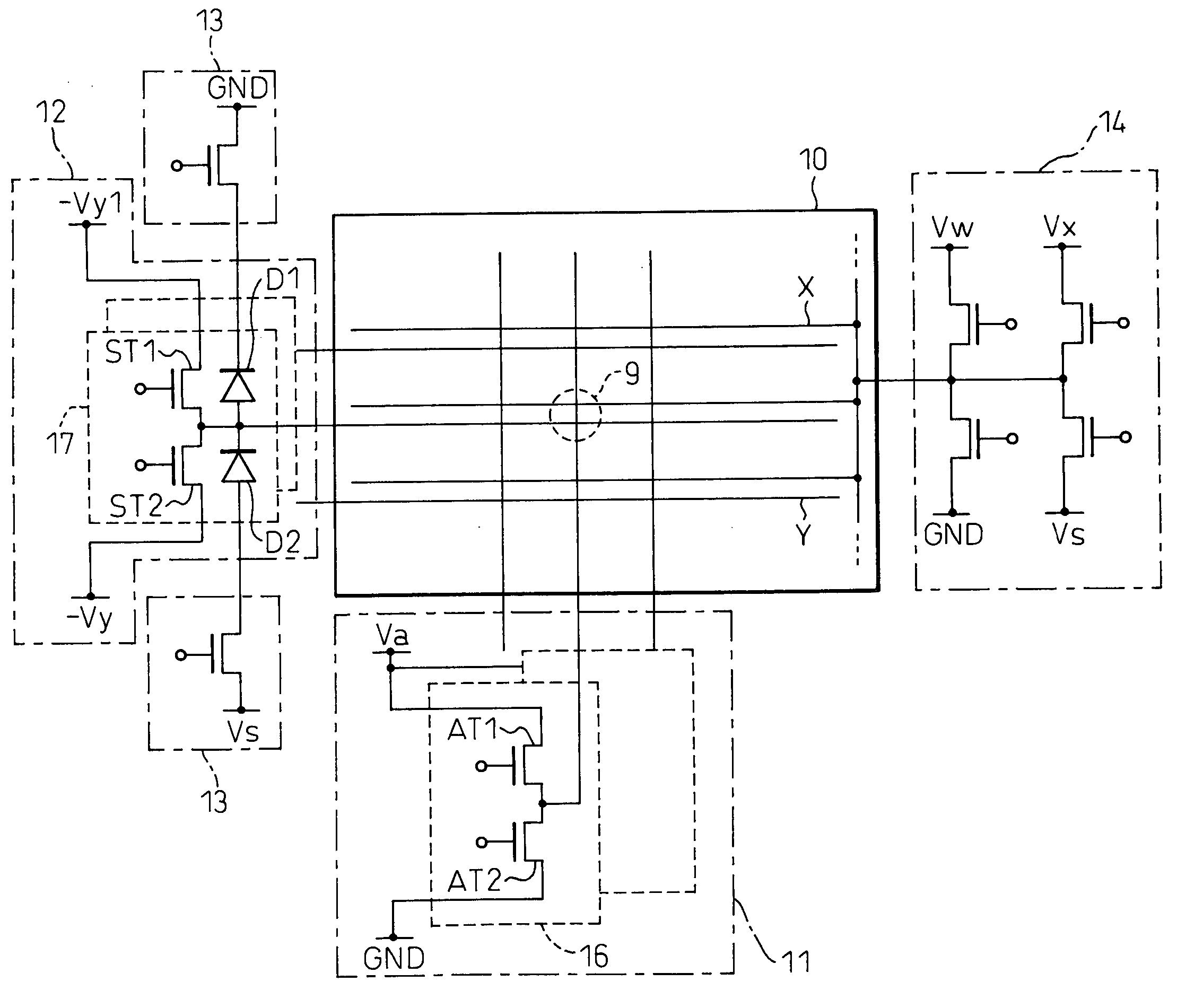
[0070] In the ALIS system plasma display panel 10, scan (Y) electrodes and sustain (X) electrodes are evenly spaced by turns and display lines are defined between respective opposite sides of the scan electrodes and the respective, adjacent sustain electrodes. The number of the sustain electrodes is one more than the number of the scan electrodes, that is, the number of the sustain electrodes is N+1 and the number of the scan electrodes is N. The ALIS s...

second embodiment

[0093] Moreover, in the second embodiment, input data that stays 1 (“H”) during one clock is inputted to the Din terminals of the first and second driver ICs 21-1 and 21-2, the carry C of the first driver IC 21-1 or the second driver IC 21-2 is inputted to the Din terminals of the third and fourth driver ICs 21-3 and 21-4, and thus the carry of the (N−1)th and N-th driver ICs is inputted to the Din terminals of the (N+1)th and (N+2)th driver ICs (N is even number and N≦24).

[0094] In other words, the configuration in the second embodiment is one in which twelve driver ICs are further provided in parallel and the outputs of the corresponding driver ICs are connected in the conventional configuration in which the 768 scan electrodes are driven by the twelve 64-bit driver ICs. Therefore, the drive waveforms of the driver IC are the same as before.

[0095] In the arrangement of the driver ICs in the second embodiment shown in FIG. 13, all of the driver ICs are provided on the same surface...

third embodiment

[0103] As described above, in the third embodiment, some of the outputs of the driver ICs are not connected to the electrodes and not used, but these unused outputs are distributed evenly to each driver IC, therefore, the amount of heat produced in each driver IC is almost the same. Because of this, it is possible to improve the operating condition of the driver ICs compared to the case where the unused outputs of the driver ICs are distributed unevenly.

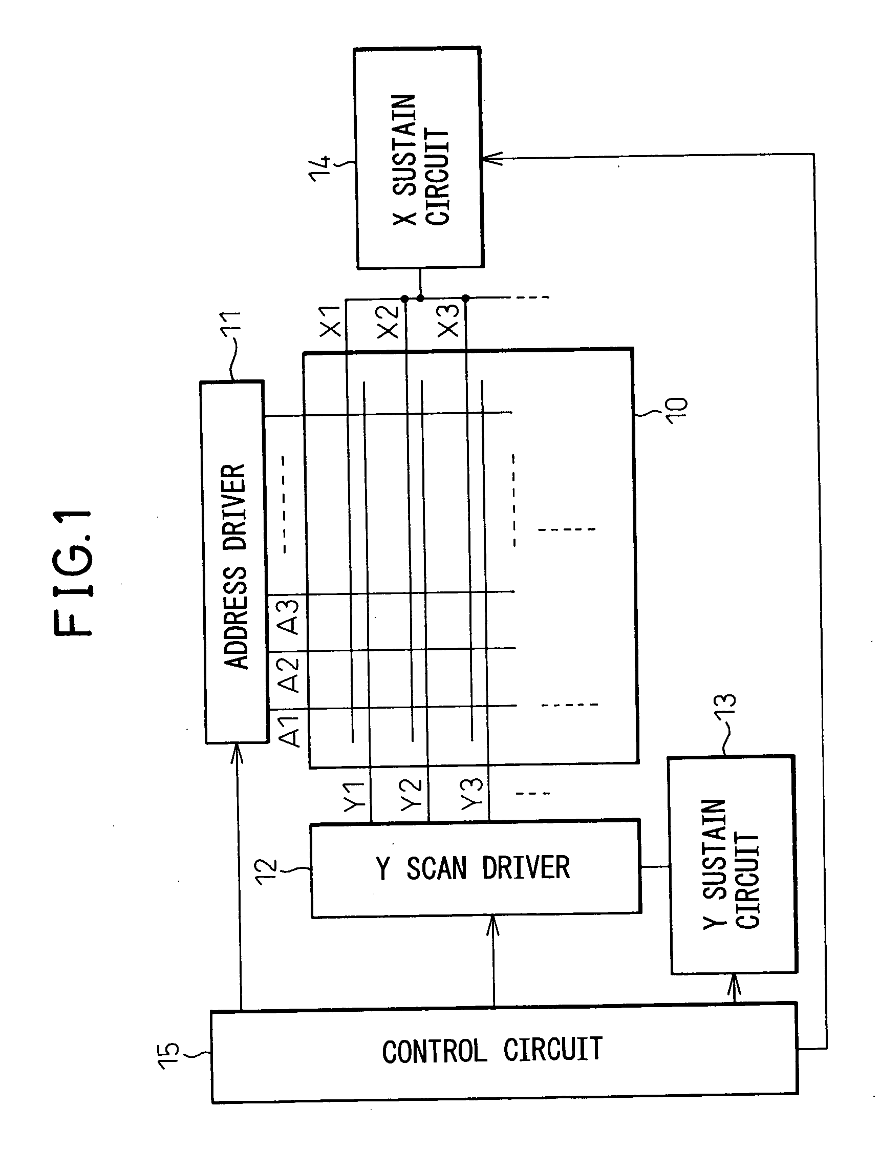
[0104]FIG. 17 is a diagram showing wiring between scan (Y) electrodes and IC outputs in the fourth embodiment of the present invention. In the fourth embodiment, a conventional plasma display panel (PDP) 10, not employing the ALIS system shown in FIG. 1, is used. The PDP 10 has 1,080 scan (Y) electrodes and 1,080 sustain (X) electrodes, respectively, and 1,080 display lines are defined. The address electrodes are not particularly limited in number.


PUM


Abstract

A PDP apparatus in which a large-sized plasma display panel, whose electrodes have large drive requirements, is driven by using already existing driver ICs, and a PDP apparatus in which the operating conditions when a plasma display panel is driven by using a plurality of driver ICs have been improved, are disclosed. According to a first aspect, one electrode of the plasma display panel is driven by combining a plurality of drive signals output from the driver IC and, according to a second aspect, in a configuration in which a plurality of electrodes are driven by a plurality of identical driver ICs, when some of a plurality of outputs of the driver ICs are not connected to the electrodes and not used, the unused outputs are distributed in each driver IC as evenly as possible.

Description

BACKGROUND OF THE INVENTION [0001] The present invention relates to a plasma display apparatus (a PDP apparatus) used as a display unit for a personal computer or work station, a flat TV, or a plasma display for displaying advertisements, information, etc. [0002] AC-type color PDP apparatuses include various types and systems such as two- or three-electrode types, an address / display non-separation system in which a period (address period) during which cells to be lit are selected and a display period (sustain period) during which a discharge is caused to occur for light emission to produce a display are shifted sequentially, and an address / display separation system in which the address period and the sustain period are separated from each other. In most systems, a PDP apparatus has at least a configuration in which a plurality of electrodes arranged in parallel to each other intersect another plurality of electrodes, and in this configuration, it is necessary to drive each electrode...

Claims


Application Information

Patent Timeline
Patent Type & Authority Applications(United States)
IPC IPC(8): G09G3/28G09G3/10G09G3/288G09G3/293G09G3/296G09G3/299H01J11/00
CPCG09G3/293G09G3/296G09G2330/045G09G2300/0426G09G2310/0218G09G3/299
Inventor OHNUKI, HIDENORIOKADA, YOSHINORI
Owner HITACHI LTD
Why Eureka
Try Eureka