Operational amplifier, line driver, and liquid crystal display device

Inactive Publication Date: 2005-04-14
MONTEREY RES LLC
View PDF3 Cites 17 Cited by
  • Summary
  • Abstract
  • Description
  • Claims
  • Application Information

AI Technical Summary

Benefits of technology

[0011] The present invention has been made to solve at least one of the problems the above prior art has. Accordingly, it is an object of the present invention to provide an op

Problems solved by technology

For example, in a source drive circuit of a liquid crystal display device in which plural operational amplifiers drive plural data lines, the output voltage of the operational amplifier is sometimes different even for an identical input voltage, which causes color shading of displayed images.
However, since a reference voltage Vref of a constant value as a reference voltage for canceling the offset of the operational amplifier is used, in a case where the voltage difference between the output vol

Method used


Image

  • Operational amplifier, line driver, and liquid crystal display device
  • Operational amplifier, line driver, and liquid crystal display device
  • Operational amplifier, line driver, and liquid crystal display device

Examples


first embodiment

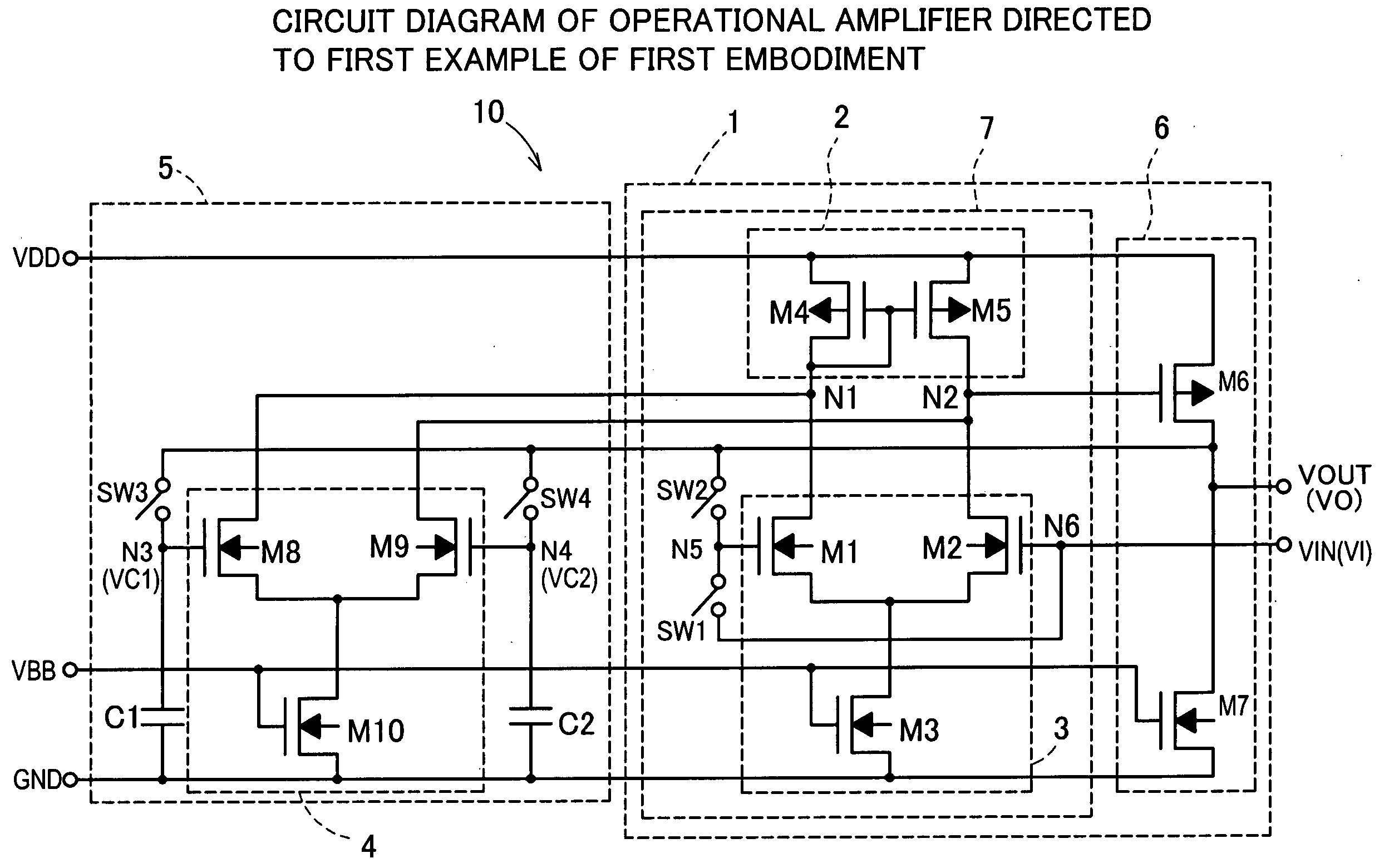
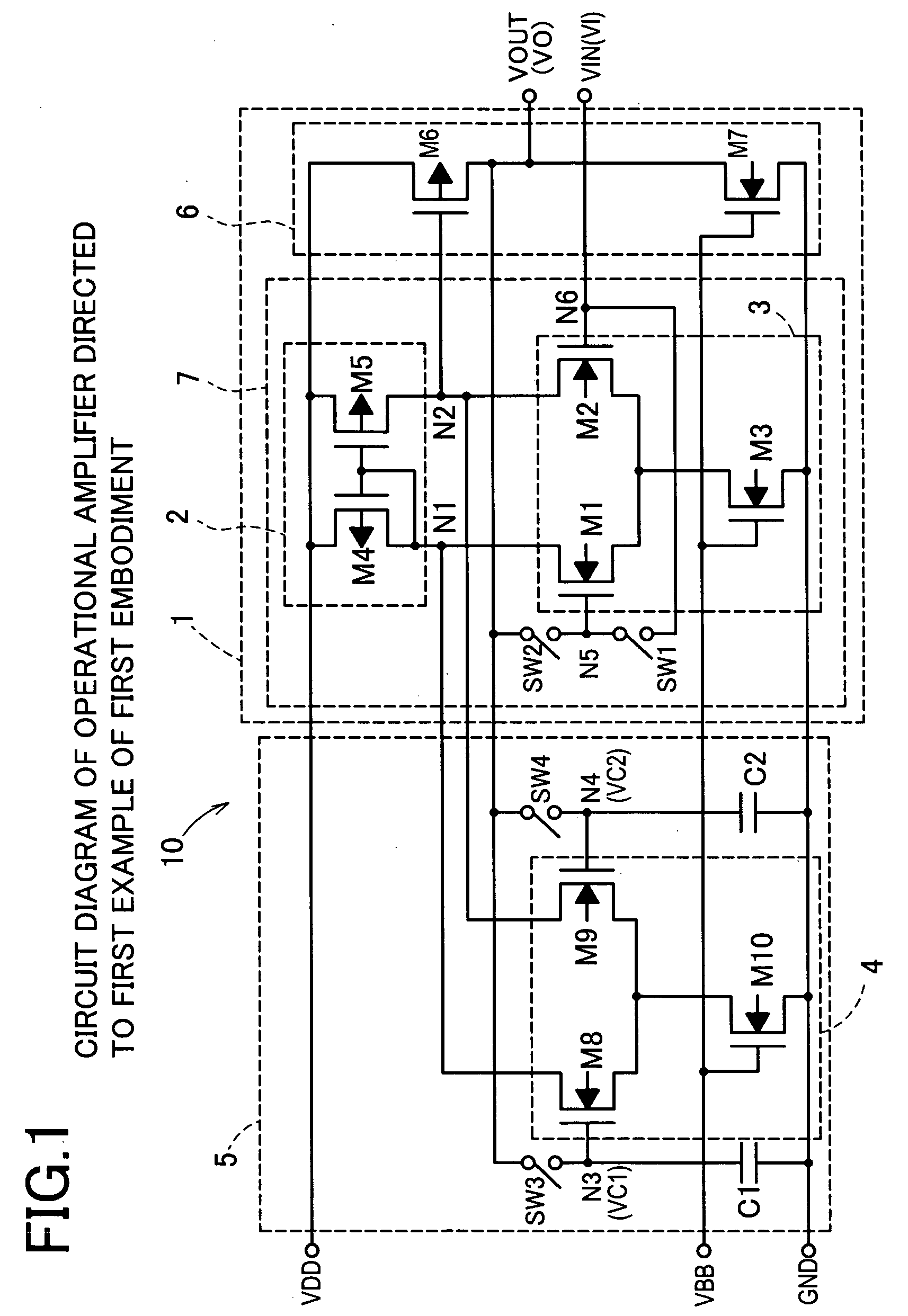
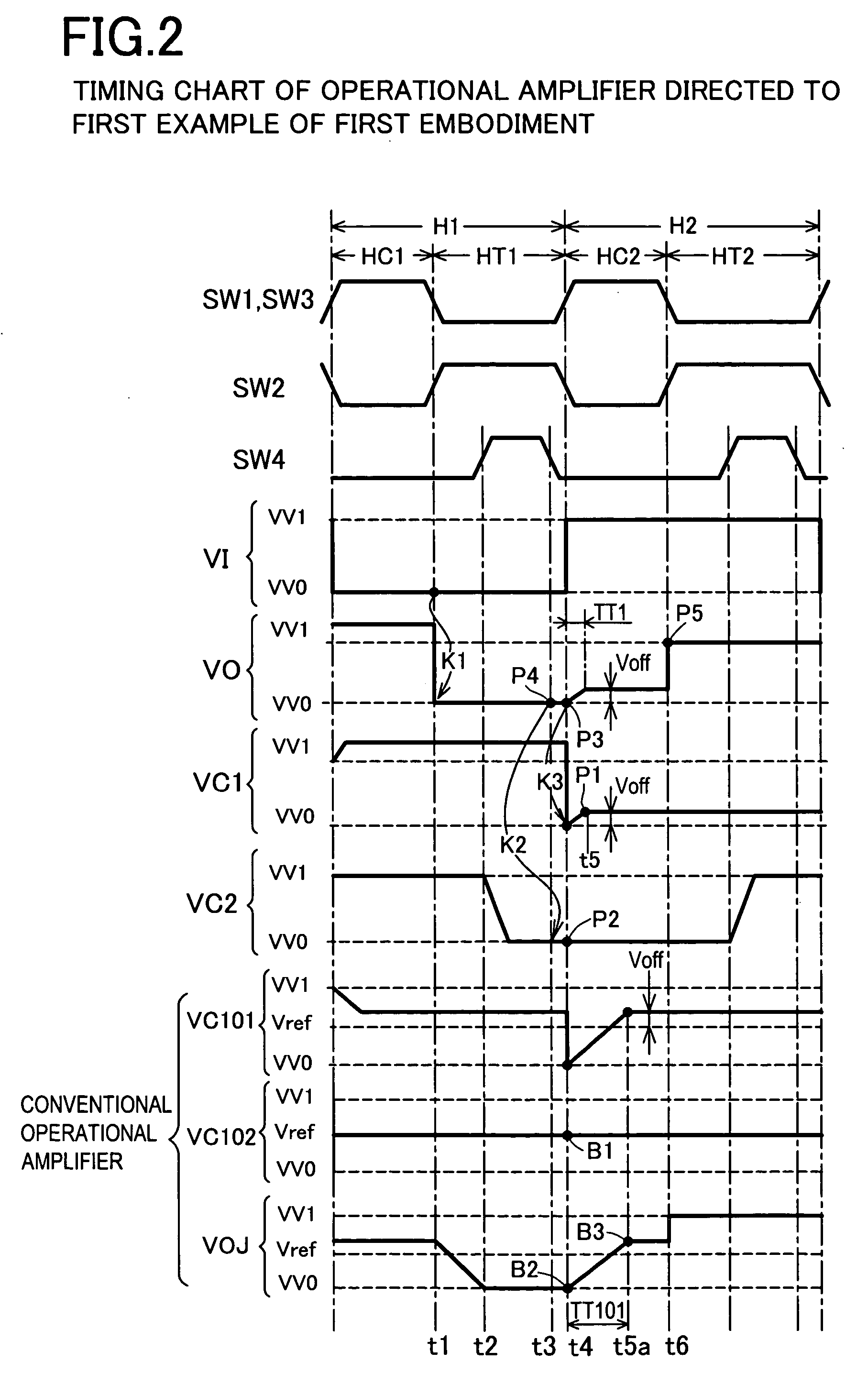
[0044] Embodiments for an operational amplifier equipped with offset cancel function, a line driver and a liquid crystal display device according to the present invention are to be described in detail with reference to the drawings based on FIG. 1 to FIG. 9. A first example in a first preferred embodiment of the invention is to be described with reference to FIG. 1 and FIG. 2. FIG. 1 shows a circuit diagram for an operational amplifier 10 having an offset cancel circuit of the The operational amplifier circuit 1 comprises a current mirror circuit 2, a first differential pair input circuit 3, and an output buffer circuit 6, and an offset cancel circuit 5 has a second differential pair input circuit 4. The current mirror circuit 2 and the first differential pair input circuit 3 constitute a differential amplifier circuit 7. The first differential pair input circuit 3 and the second differential pair input circuit 4 are connected at a first current terminal N1 and a second current ter...

second embodiment

[0063] A second embodiment for a liquid crystal display device driving circuit and a liquid crystal display device using the operational amplifiers of the invention are to be described. A method of constituting voltage followers 131 equipped with offset cancel in a line driver 130 in a liquid crystal display device as shown in FIG. 12 is extracted and schematically shown in FIG. 13. In the line driver 130, plural input and output terminal are arranged in one block and the blocks are arranged by the number corresponding to the number of pixels to constitute the line driver 130. FIG. 13 shows a block 135 having 6-input and 6-output as an example. The block 135 has data input terminals DIJ1 to DIJ6 and data output terminals DOJ1 to DOJ6. Display data D1 to D6 are inputted from a control circuit 150 (FIG. 12) to the data input terminals DIJ1 to DIJ6, and outputted from the data output terminals DOJ1 to DIJ6 to respective corresponding data lines 121. Further, operational amplifiers AJ1 ...


PUM


Abstract

An operational amplifier capable of offset cancel in a shorter period, as well as a line driver capable of shortening one horizontal period and a liquid crystal display device are provided. In the operational amplifier of the invention, a time necessary for feed back control can be shortened than usual by a constitution that an output voltage VO in one horizontal period H1 which is one horizontal period before is defined as a reference voltage in an offset cancel preparatory period HC2, thereby changing the output voltage VO(2) only by the offset voltage VO(2) by the feed back control. In the line driver of the invention, the operational amplifier not used for the output of display data D1 to D6 conducts offset cancel operation and it is successively shifted on every one horizontal period. Since it is no more necessary to incorporate the offset cancel preparatory period in the output period, one horizontal period can be shortened further.

Description

CROSS-REFERENCE TO RELATED APPLICATIONS [0001] This application is based upon and claims the benefit of priority from each of the prior Japanese Patent Application No. 2003-352203 filed on Oct. 10, 2003, the entire contents of which are incorporated herein by reference. BACKGROUND OF THE INVENTION [0002] 1. Field of the Invention [0003] The present invention concerns an operational amplifier equipped with an offset cancel function. Further, it also relates to a line driver for a liquid crystal display device equipped with an offset cancel function and a liquid crystal display device [0004] 2. Description of Related Art [0005] In an operational amplifier, an offset voltage is sometimes generated by scattering of current-voltage characteristics of constitutional transistors. Generation of the offset voltage is not preferred in view of characteristics of the operational amplifier. For example, in a source drive circuit of a liquid crystal display device in which plural operational ampl...

Claims


Application Information

Patent Timeline
IPC IPC(8): G09G3/36G09G3/20H03F3/45
CPCH03F3/45753G09G3/3688G09G3/36
Inventor KASAI, TOSHIHIKOUDO, SHINYAKOKUBUN, MASATOSHIKIZAKI, YOSHIHIRO
Owner MONTEREY RES LLC
Why Eureka
Try Eureka