Integrated optical assembly

Active Publication Date: 2005-04-14
II VI DELAWARE INC
View PDF5 Cites 54 Cited by
  • Summary
  • Abstract
  • Description
  • Claims
  • Application Information

AI Technical Summary

Benefits of technology

[0019] Exemplary implementations of the present invention are directed to systems, apparatus, and methods for integrating multiple transceiver components into an optical assembly, such as a TOSA, a ROSA, or combined transmitter/receiv

Problems solved by technology

This in turn reduces the number and significance of p

Method used


Image

  • Integrated optical assembly
  • Integrated optical assembly
  • Integrated optical assembly

Examples


Embodiment Construction

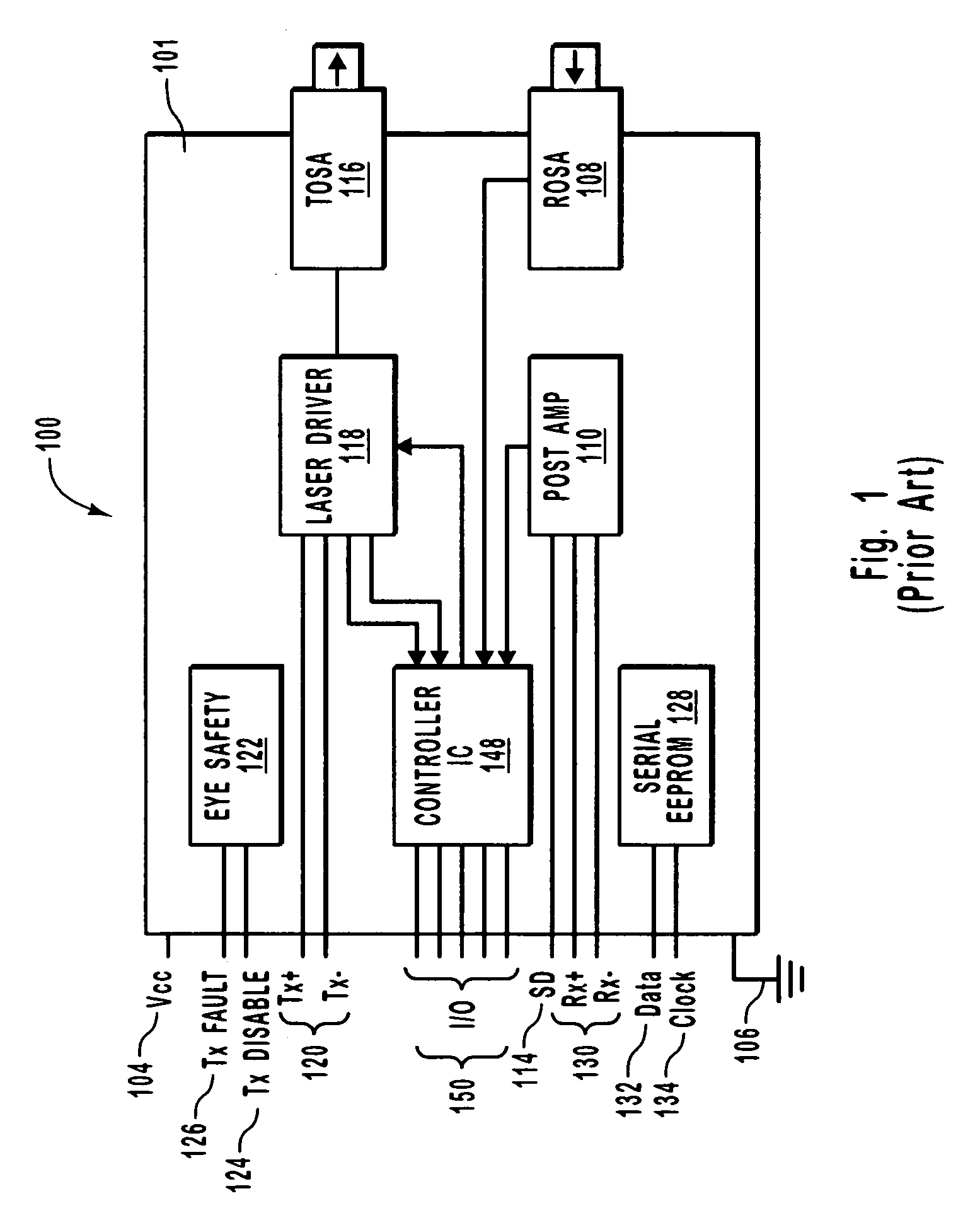
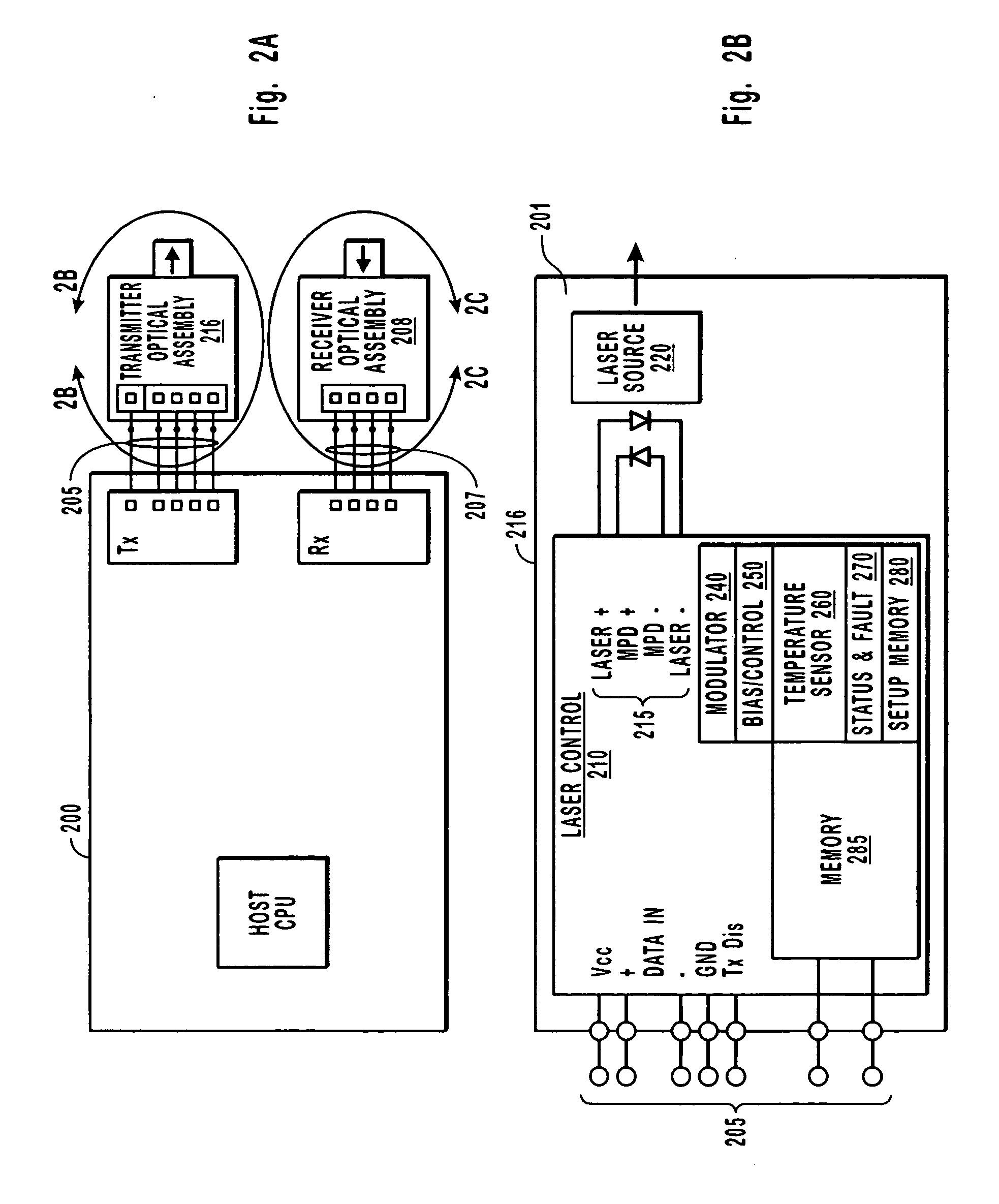
[0029]FIG. 2A illustrates a schematic overview for practicing at least one embodiment of the present invention. In contrast with the prior art shown in FIG. 1, FIG. 2A shows a direct connection between an optical assembly such as a transmitter assembly 216 or a receiver assembly 208 and a host 200. In particular, the present invention can allow total removal of a transmitter, receiver, or transceiver IC component since much or all of the active and / or passive circuitry otherwise used to drive a respective transmitter, receiver, or transceiver IC optical component is placed substantially within what would otherwise be the TOSA, ROSA, or combined OSA.

[0030] Accordingly, the term TOSA, ROSA, or OSA is not limited to a “subassembly” that is mounted on an IC, such as a transceiver IC, etc. For example, in some cases the specific optical component may or may not be separately “sub-assembled”, such as onto a transmitter, receiver, or combination transmitter / receiver substrate IC. Thus, fo...


PUM


Abstract

An integrated fiber optic assembly includes some of the active components that are otherwise found in a typical transceiver. For example, a transmitter optical assembly includes a laser source, a laser driver, and a component for administering diagnostic data. A receiver optical assembly includes a photo-diode an optical converter, such as a transimpedance amplifier, and a processing control that can administer, for example diagnostic data associated with the receiver optical assembly. A combination optical assembly includes a photo-diode and a laser source, as well as many of the active components for driving, operating, or administering the laser source. In part since the active components can be placed in close proximity to each other, electrical impedance is reduced that would otherwise be present in a typical transceiver and optical subassembly.

Description

CROSS-REFERENCE TO RELATED APPLICATIONS [0001] This invention claims priority to provisional patent application Ser. No. 60 / 509,932, entitled “INTEGRATED OPTICAL ASSEMBLY”, filed on Oct. 2, 2003, which is incorporated herein in its entirety by reference.BACKGROUND OF THE INVENTION [0002] 1. The Field of the Invention [0003] The invention generally relates to systems and apparatus for overcoming discontinuities present in conductive pathways on optical transceivers. [0004] 2. The Relevant Technology [0005] Fiber optic technology is increasingly employed as a method by which information can be reliably transmitted via a communications network. Networks employing fiber optic technology are known as optical communications networks, and are marked by high bandwidth and reliable, high-speed data transmission. [0006] Optical communications networks employ optical transceivers in transmitting information via the network from a transmitting node to a receiving node. Generally, optical transc...

Claims


Application Information

Patent Timeline
IPC IPC(8): H04B10/12H04B10/24
CPCH04B10/40
Inventor HOSKING, LUCY G.
Owner II VI DELAWARE INC
Why Eureka
Try Eureka