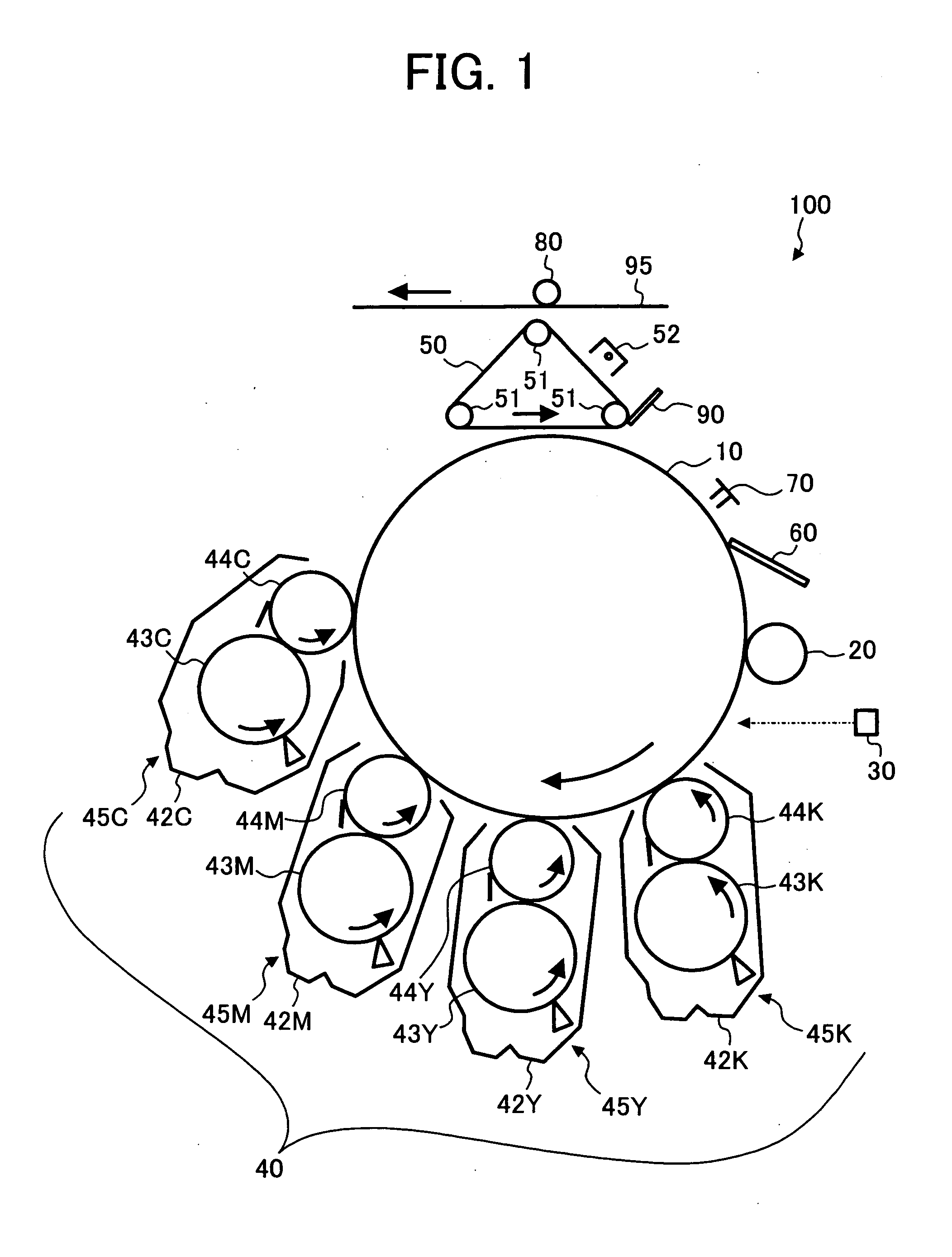
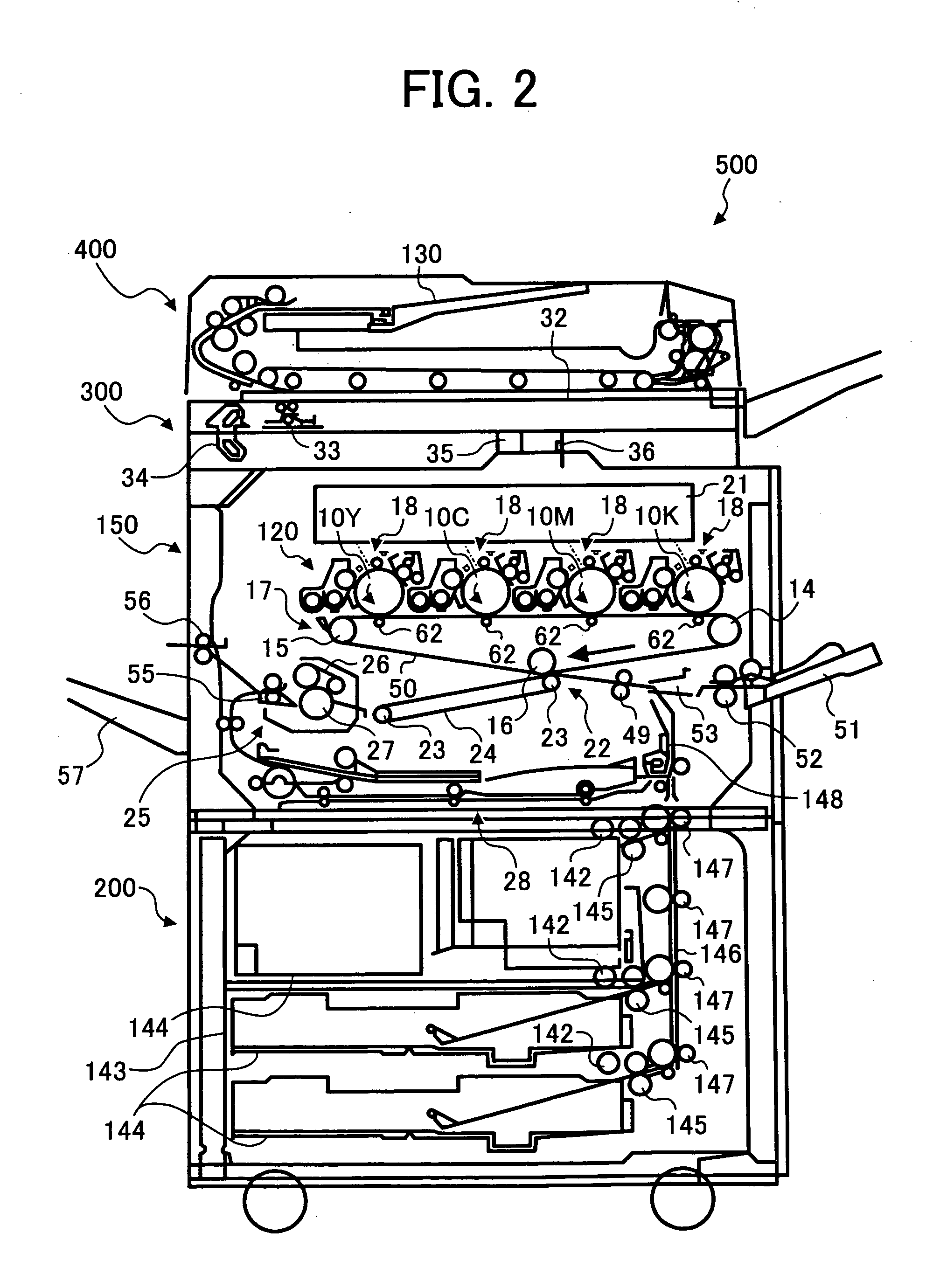
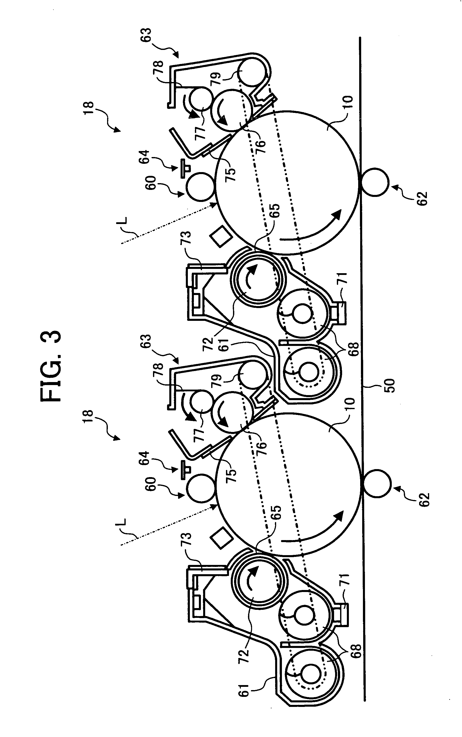
Toner, method for manufacturing the toner, developer including the toner, container containing the toner, and image forming method and apparatus and process cartridge using the toner

a technology of toner and developer, which is applied in the field of toner, can solve the problems of inability to prepare toner particles having such a small particle diameter, inability to remove toner particles remaining on the surface of photoreceptors, and increase manufacturing costs, and achieves the effect of high quality

Inactive Publication Date: 2005-04-14
RICOH KK
View PDF21 Cites 60 Cited by
  • Summary
  • Abstract
  • Description
  • Claims
  • Application Information

AI Technical Summary

Benefits of technology

Accordingly, an object of the present invention is to provide an image forming method and an image forming apparatus by which hi

Problems solved by technology

However, when it is tried to prepare a toner having a small particle diameter using such a pulverization method to produce high quality images, problems which occur are that the manufacturing costs increase and/or a toner having such a small particle diameter cannot be prepared because there is a limit of pulverization ability of pulverizers.
In addition, published unexamined Japanese patent application No.
However, these toners (i.e., toners prepared by the polymerization methods and the polymer solution suspension methods) typically have a spherical form, and therefore a cleaning problem occurs in that toner particles remaining on

Method used


Image

  • Toner, method for manufacturing the toner, developer including the toner, container containing the toner, and image forming method and apparatus and process cartridge using the toner
  • Toner, method for manufacturing the toner, developer including the toner, container containing the toner, and image forming method and apparatus and process cartridge using the toner
  • Toner, method for manufacturing the toner, developer including the toner, container containing the toner, and image forming method and apparatus and process cartridge using the toner

Examples


example 1

Preparation of Toner Binder

The following components were contained in a reaction container having a condenser, a stirrer and a nitrogen introducing tube to perform a polycondensation reaction for 8 hours at 230° C. under normal pressure.

Adduct of bisphenol A with 2 mole of724partsethylene oxideTerephthalic acid276partsDibutyl tin oxide2parts

Then the reaction was further continued for 5 hours under a reduced pressure of from 10 to 15 mmHg. Thus, an unmodified polyester resin having a peak molecular weight of 4800 was prepared.

Then 10 parts of trimellitic anhydride were added to the unmodified polyester resin and the mixture was reacted at 200° C. for 2 hours under a reduced pressure of from 10 to 15 mmHg to replace the hydroxyl group present at the end portion of the unmodified polyester resin with a carboxyl group.

One hundred (100) parts of the thus prepared polyester resin were dissolved in 100 parts of ethyl acetate to prepare an ethyl acetate solution of the binder resi...

example 2

The procedure for preparation of the toner in Example 1 was repeated except that in the wet external addition process the mixture of the particulate silica dispersion and the toner particle dispersion was agitated for 1 hour at 50° C.

Thus, a toner of Example 2 was prepared. The toner was also evaluated in the same way as mentioned in Example 1. The results are shown in Tables 1 and 2.

The toner particles were observed and photographed using a scanning electron microscope. As a result, it was confirmed that a particulate silica having an average particle diameter of about 0.12 μm is uniformly adhered to the surface of the toner particles while slightly embedded to the toner particles.


PUM


Abstract

An image forming method including forming an electrostatic latent image on an image bearing member; developing the electrostatic latent image with a developer including a toner to prepare a toner image on the image bearing member; transferring the toner image onto a receiving material; and cleaning the surface of the image bearing member with a cleaning blade; wherein a surface of the image bearing member has a friction coefficient of from 0.10 to 0.40, and wherein the toner has an average circularity of from 0.97 to 1.00 and includes toner particles and a particulate material having an average particle diameter of from 0.03 to 1 μm, wherein the particulate material is externally added to the toner particles by a wet method.

Description

BACKGROUND OF THE INVENTION 1. Field of the Invention The present invention relates to a toner for use in developing an electrostatic latent image formed by a method such as electrophotography, electrostatic recording and electrostatic printing. In addition, the present invention also relates to a method for preparing the toner, a developer including the toner, a container containing the toner, and an image forming method, an image forming apparatus and a process cartridge using the toner. 2. Discussion of the Background Electrophotographic image forming methods are widely used for image forming apparatus such as copiers, facsimile machines and laser printers. As described in U.S. Pat. No. 2,297,691 and published examined Japanese patent application No. 43-24748, the electrophotographic image forming methods typically include the following processes: (1) charging an image bearing member (e.g., photoreceptors) (charging process); (2) irradiating the photoreceptor with imagewise...

Claims


Application Information

Patent Timeline
IPC IPC(8): G03G5/04G03G5/043G03G5/147G03G9/08G03G9/087G03G9/097
CPCG03G5/04G03G5/043G03G5/147G03G5/14704G03G5/14713G03G9/0815G03G9/09791G03G9/08782G03G9/09708G03G9/09716G03G9/09725G03G9/09733G03G9/09783G03G9/0827
Inventor WATANABE, YOHICHIROHYAMASHITA, HIROSHISUGIYAMA, TSUNEMIOHTANI, SHINJISAITO, TAKUYAKAMI, HIDETOSHI
Owner RICOH KK
Why Eureka
Try Eureka