Cell phone and built-in antenna thereof

a cell phone and antenna technology, applied in the field of cell phones, can solve the problems of low density, achieve the effects of suppressing the variation in the dimension of mass production, reducing the physical size of the antenna element, and reducing the weigh

Inactive Publication Date: 2005-04-14
MITSUBISHI ELECTRIC CORP
View PDF16 Cites 16 Cited by
  • Summary
  • Abstract
  • Description
  • Claims
  • Application Information

AI Technical Summary

Benefits of technology

[0018] It is an object of the present invention to solve the problems described above and to properly reduce a physical size of an antenna element, to decrease a weight and satisfy an impact resistance, to suppress a variation in a dimension in mass production, and to set speech quality to a level having no problem in consideration of an actual use state in which a hand or the like approaches in a built-in antenna of a cell phone.
[0020] Consequently, an antenna element having a proper size and a high performance can be formed in the cell phone and a necessary bandwidth ratio can be obtained, and speech quality is not greatly influenced even if a variation in an assembly of mass production and an influence of a hand in actual use are taken into consideration. Moreover, the styrene type rubber, the polyolefin type rubber or both of them is / are blended with the cyclo-olefin polymer. Therefore, a sufficient impact strength is obtained and a clearance between the antenna element and an inner part of a housing does not need to be taken excessively. Thus, a dimension of an appearance of the cell phone can be more reduced than that in the case in which a material having a small impact strength is to be used. Furthermore, a density is low. Consequently, a weight of the antenna element can be reduced, and furthermore, a great contribution to a reduction in a weight of the cell phone can be made.

Problems solved by technology

Furthermore, a density is low.

Method used


Image

  • Cell phone and built-in antenna thereof
  • Cell phone and built-in antenna thereof
  • Cell phone and built-in antenna thereof

Examples


first embodiment

1. FIRST EMBODIMENT

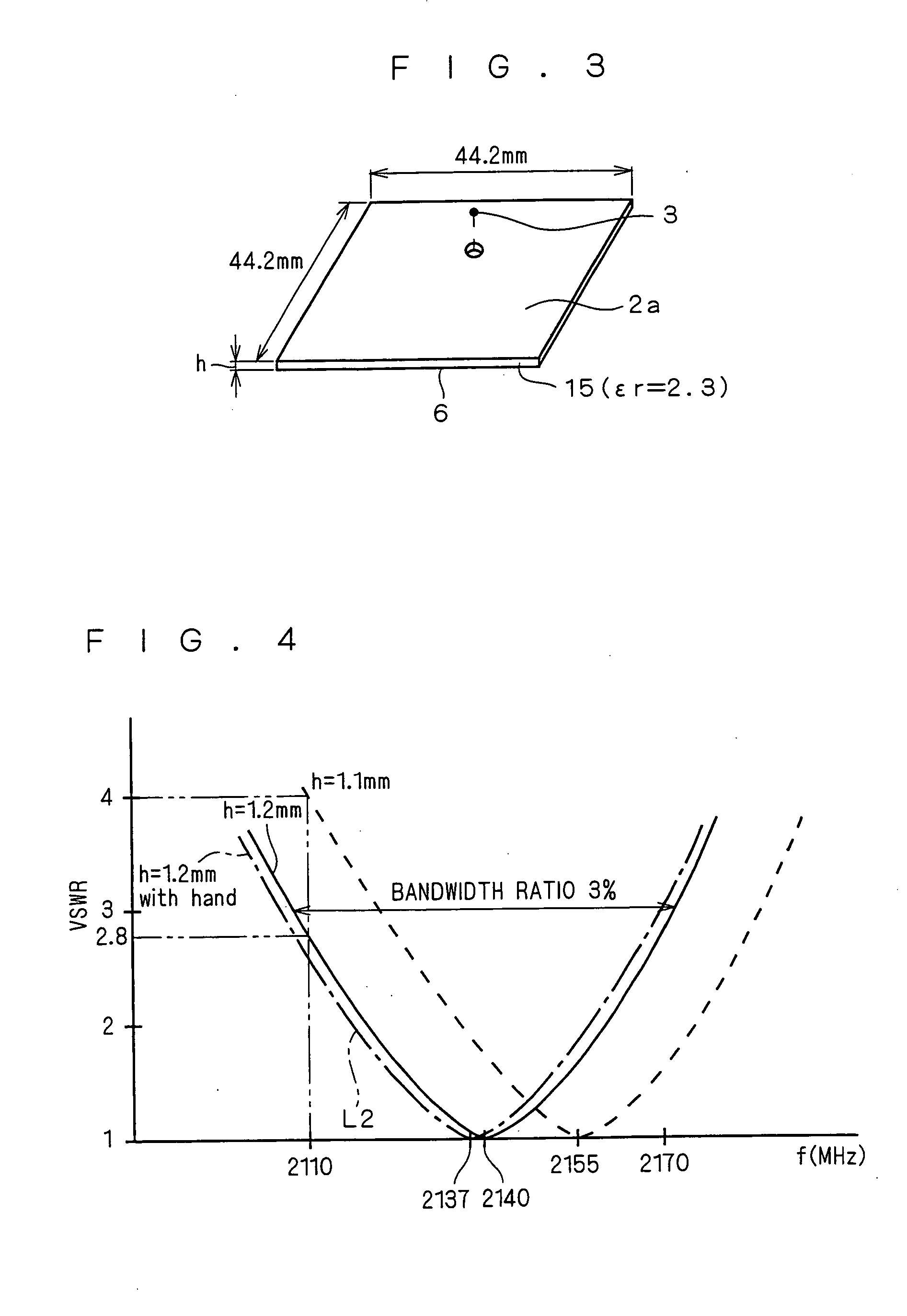
[0042] In a built-in antenna of a cell phone, generally, the inventor examined conditions of a characteristic required for a material of a dielectric between an antenna element and a ground. As a result, the following items (1) to (6) can be given. [0043] (1) A relative dielectric constant is equal to or smaller than 3, [0044] (2) a dielectric dissipation factor is low, that is, 0.0002 or less, [0045] (3) plating can be carried out by an MID (Molded Interconnection Device) or a printing method, [0046] (4) an impact strength is at least equal to or greater than that (30J) of ABS (Acrylonitrile-butadiene-styrene) which is generally used in a cell phone, [0047] (5) a heat resistance to solder reflow is held, and [0048] (6) a density is low.

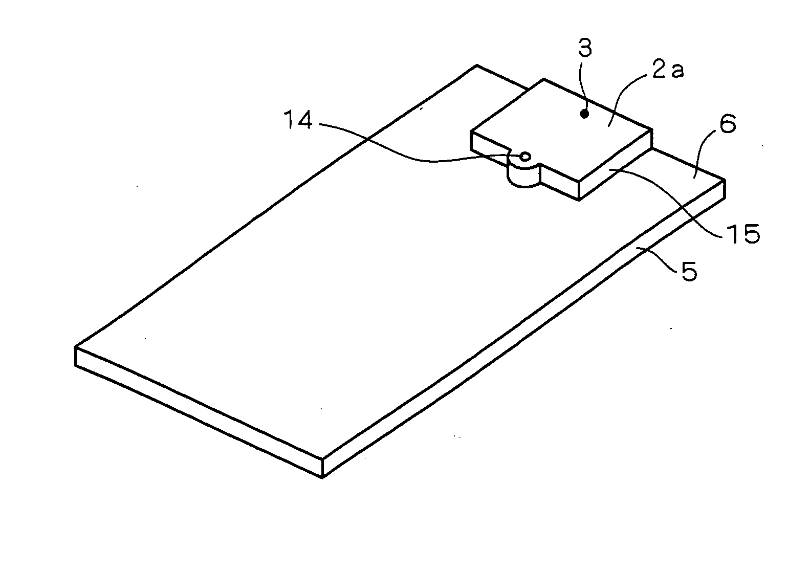
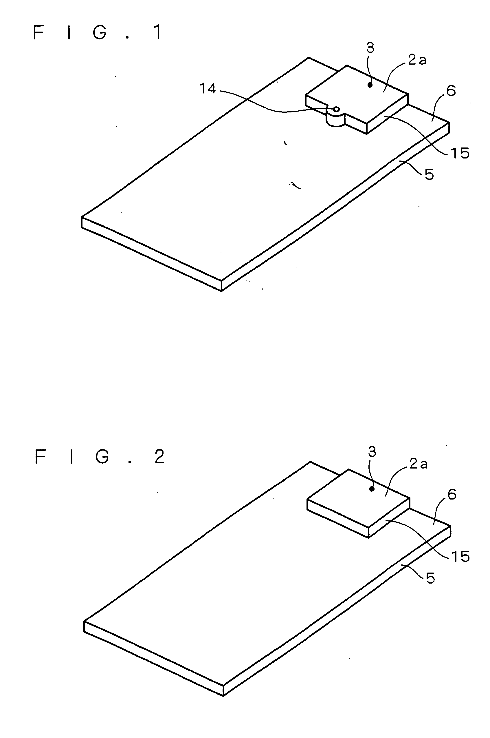
[0049] The inventor examined a material which can be used as an antenna element (the designation 2a in FIGS. 1 and 2) of a built-in antenna. As a result, it was found that materials listed in the following Table 1 can be given.

T...

second embodiment

2. SECOND EMBODIMENT

[0065] While the COP (Cyclo-olefin polymer) 15 to be a block-shaped dielectric in the plating grade which is subjected to the resin plating by the MID (Molded Interconnection Device) is applied as the antenna element 2a in the first embodiment, the same effects as those in the first embodiment can be obtained even if the block-shaped COP (Cyclo-olefin polymer) 15 subjected to the resin plating by a printing method is applied in place of such a structure. Also in this case, it is preferable that the antenna element 2a should be fixed onto the ground 6 of the circuit board 5 as shown in FIGS. 1 and 2.

third embodiment

3. THIRD EMBODIMENT

[0066] While the antenna element 2a is formed on the COP 15 in the plating grade and is fixed to the ground 6 provided on the circuit board 5 in each of the embodiments, for example, it is also possible to employ such a structure that a shield box for shielding a noise in which the ground 6 is to be provided is formed by the COP (Cyclo-olefin polymer) 15 in the plating grade and the antenna element 2a and the shield box (ground 6) are plated by an MID (Molded Interconnection Device), a printing method or the like in the case in which the circuit board 5 in which the ground 6 is not formed is covered with the shield box from above in FIGS. 1 and 2 and a metal for shielding of the shielding box also serves as the ground 6. Thus, it is not necessary to combine the shield box and the antenna element 2a as separate members. Therefore, precision in an assembly can be prevented from being varied and it is sufficient that only precision in molding is considered. According...


PUM


Abstract

A cell phone including a built-in antenna, the cell phone having a reduced physical size of an antenna element, a decreased weight and satisfying an impact resistance, and suppressing a variation in a dimension caused by mass production and considering an actual use state in which a hand or the like approaches. A dielectric between an antenna element and a ground is a support member of a cyclo-olefin polymer in a plating grade having an impact resistance which is obtained by blending styrene type rubber, polyolefin type rubber (elastomer) or both of them, and the antenna element is constituted by a plating formed on a main surface of the dielectric.

Description

TECHNICAL FIELD [0001] The present invention relates to a cell phone comprising a built-in antenna and the built-in antenna. BACKGROUND ART [0002]FIG. 6 shows an example (a conventional example 1) of a conventional cell phone comprising a built-in antenna. In the cell phone according to the conventional example 1, as shown in FIG. 6, a phosphor bronze plate or the like is plated with nickel for an anticorrosive treatment, and furthermore, is plated with gold to form an antenna element 2, and the antenna element 2 is stuck to an internal surface of a body rear case 1 with a double-sided tape or the like. In FIG. 6, the reference numeral 4 denotes a connection part to be connected to a power feeding point 3 of the antenna element 2, the reference numeral 5 denotes a circuit board mounting a radio communication circuit, a liquid crystal display portion (LCD) and various operation keys and the like (not shown), the reference numeral 6 denotes a ground part of the circuit board 5, the re...

Claims


Application Information

Patent Timeline
Patent Type & Authority Applications(United States)
IPC IPC(8): H01Q1/24H01Q1/38H01Q1/52H01Q9/04
CPCH01Q1/38H01Q1/243H01Q1/24H04B1/38
Inventor TAKETOMI, HIROKAZUBABA, FUMIAKISUNAHARA, YONEHIKOIMANISHI, YASUHITOTANAKA, TETSUYA
Owner MITSUBISHI ELECTRIC CORP
Why Eureka
Try Eureka