Method and system for determining the location of a medical probe using a reference transducer array

a technology of reference transducer array and medical probe, which is applied in the field of medical probes, can solve the problems of difficulty in identifying features of the anatomy limited use of fluoroscopy in locating catheters, and difficulty for physicians to visualize anatomy features as a reference for navigation,

Inactive Publication Date: 2005-04-14
BOSTON SCI SCIMED INC
View PDF40 Cites 52 Cited by
  • Summary
  • Abstract
  • Description
  • Claims
  • Application Information

AI Technical Summary

Problems solved by technology

The use of fluoroscopy in locating catheters is somewhat limited, however, in that the physician is only able to visualize the catheter and surrounding tissues in two dimensions.
In addition, fluoroscopy does not image soft tissues, making it difficult for the physician to visualize features of the anatomy as a reference for the navigation.
Although real-time three-dimensional imaging systems, such as the SONOS 7500, provide high resolution images, these types of imaging systems are somewhat limited in the field of electrophysiology therapy, because t

Method used


Image

  • Method and system for determining the location of a medical probe using a reference transducer array
  • Method and system for determining the location of a medical probe using a reference transducer array
  • Method and system for determining the location of a medical probe using a reference transducer array

Examples


Embodiment Construction

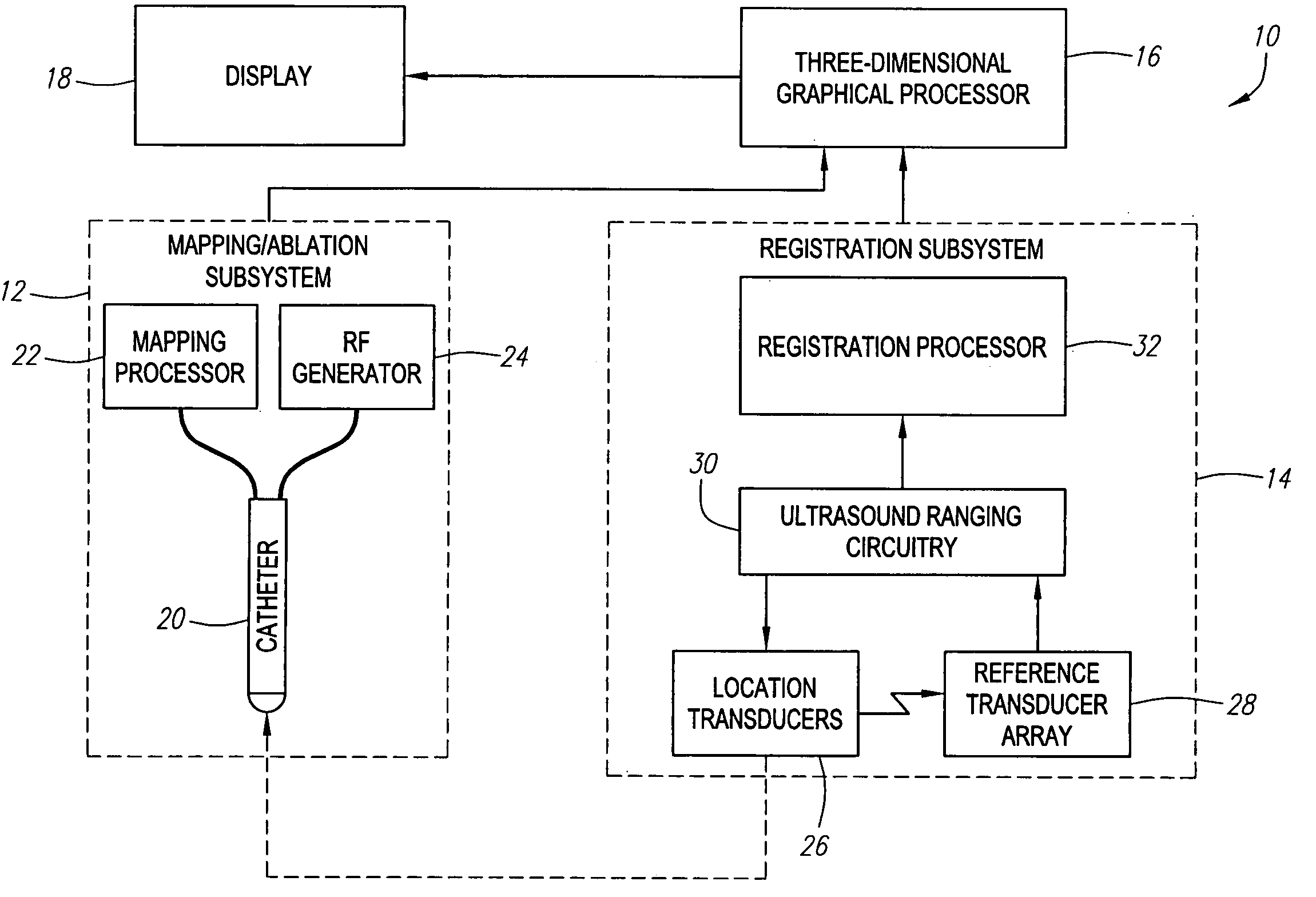
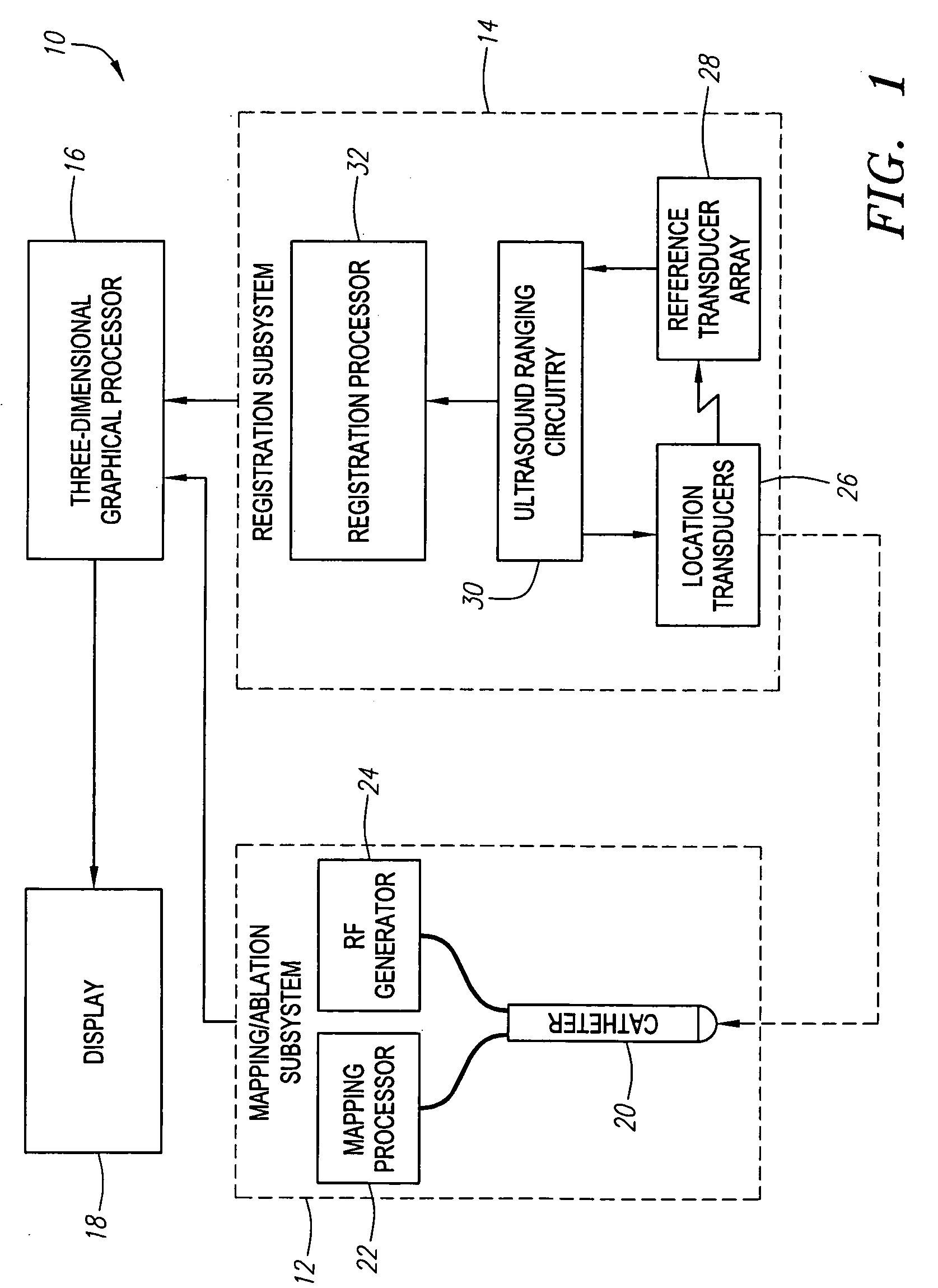
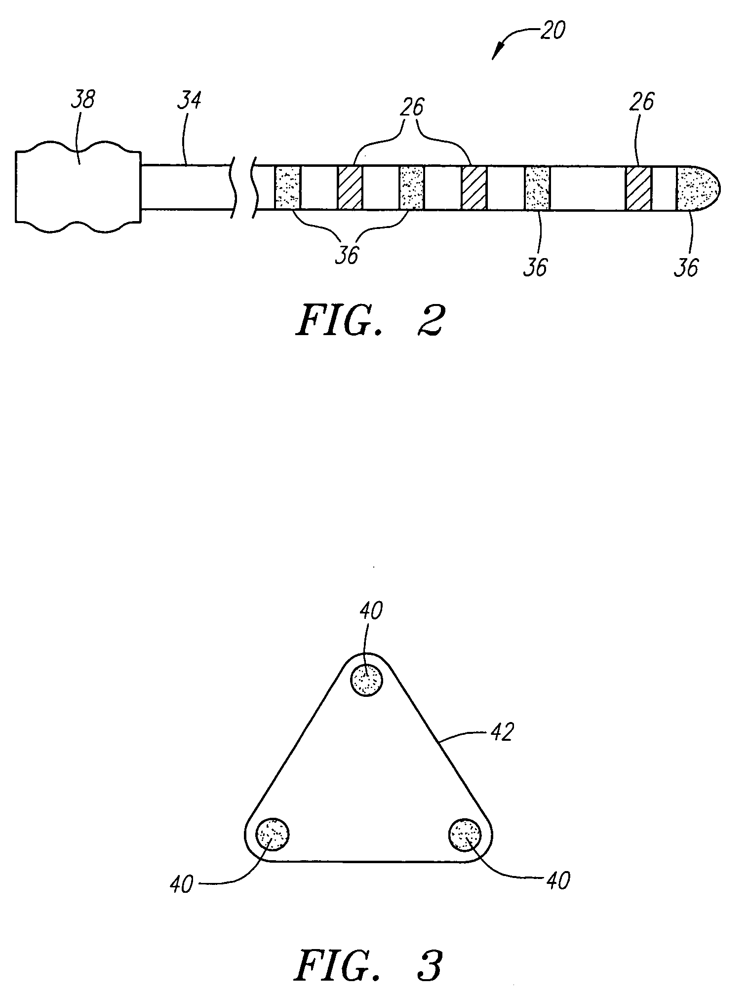
Referring to FIG. 1, an exemplary medical treatment system 10 constructed in accordance with the present invention is shown. The treatment system 10 is particularly suited for mapping and treating the heart. Nevertheless, it should be appreciated that it can be used for treating other internal anatomical structures, e.g., the prostrate, brain, gall bladder, uterus, esophagus and other regions in the body. The treatment system 10 generally comprises (1) a mapping / ablation subsystem 12 for mapping and ablating tissue within the heart; (2) a registration subsystem 14 for registering mapping data and the movement of a probe within a three-dimensional graphical environment; (3) a three-dimensional graphical processor 16 for generating three-dimensional graphical data of the environment in which the mapping data is obtained; and (4) a display 18 for displaying the graphical image. It should be noted that the elements illustrated in FIG. 1 are functional in nature, and are not meant to li...


PUM


Abstract

The present invention provides systems and methods for determining the coordinates of a location element mounted on a medical probe. First and second signals are transmitted between the location element and a first and second reference transducers, which may be arranged in a reference array that can be attached to a patient's skin. A transit time difference between the first and second signals is determined, e.g., using a thresholding or correlation technique. A distance difference between a first distance extending from the location element to the first reference element and a second distance extending from the location element to the second reference element is then determined based on the transit time difference. An angle between the reference array and the location element can then be determined based on the determined distance difference and a known distance between the first and second reference transducers. The coordinates of the location element within a coordinate system are then determined based on the determined angle and the distance between the transducer array and the location element.

Description

FIELD OF THE INVENTION The present inventions generally relate to medical probes, and more particularly to systems and methods for determining the location of a medical probe. BACKGROUND OF THE INVENTION It is often necessary or desirable to determine the location of a medical probe when performing a diagnostic and / or therapeutic procedure on a patient. As one example, catheters, whether intravascular or extravascular, must typically be navigated through a patient's body in order to locate the operative portion of the catheter adjacent a target tissue region. Traditionally, this has been accomplished using fluoroscopy. In this case, radiopaque elements are located on the distal end of the catheter and fluoroscopically imaged as the catheter is routed through the body. As a result, a two-dimensional image of the catheter, as represented by the illuminated radiopaque elements, thereby allowing the physician to roughly determine the location of the catheter. The use of fluoroscopy in...

Claims


Application Information

Patent Timeline
IPC IPC(8): A61B18/14A61B19/00G01S5/22
CPCA61B18/1492A61B19/52A61B19/5244A61B2017/00044G01S5/22A61B2019/5263A61B2019/5272A61B2019/5276A61B2019/5291A61B2018/00839A61B34/20A61B90/36A61B2034/2063A61B2034/2072A61B2090/365A61B2090/378
Inventor WILLIS, PARKER
Owner BOSTON SCI SCIMED INC
Why Eureka
Try Eureka