Lead body construction

a lead body and lead technology, applied in the field of implantable medical devices, can solve the problems of body size and the tendency of the lead to move in a “whip-like” fashion within the heart chamber, and achieve the effect of reducing the “whip-like” action and stiffness of the lead

Inactive Publication Date: 2005-04-14
PACESETTER INC
View PDF22 Cites 69 Cited by
  • Summary
  • Abstract
  • Description
  • Claims
  • Application Information

AI Technical Summary

Benefits of technology

Yet a further feature of the present invention is the provision of such an improved lead assembly which employs inner insulation of PTFE to provide stiffness to the lead and thereby alleviate the “whip-like” action which often occurs with small sized leads implanted in the chambers of the heart.
Yet another feature of the present invention is the provision of such an improved lead assembly in which the lead body has varying flexibility or stiffness along its length.

Problems solved by technology

However, an identified drawback in downsizing the lead body size is the tendency for the lead to rapidly move within the heart chamber in a “whip-like” fashion.
Furthermore, with increasing complexity of lead systems, there is a growing need for ease of manufacturability of a lead system.

Method used


Image

  • Lead body construction
  • Lead body construction
  • Lead body construction

Examples


Embodiment Construction

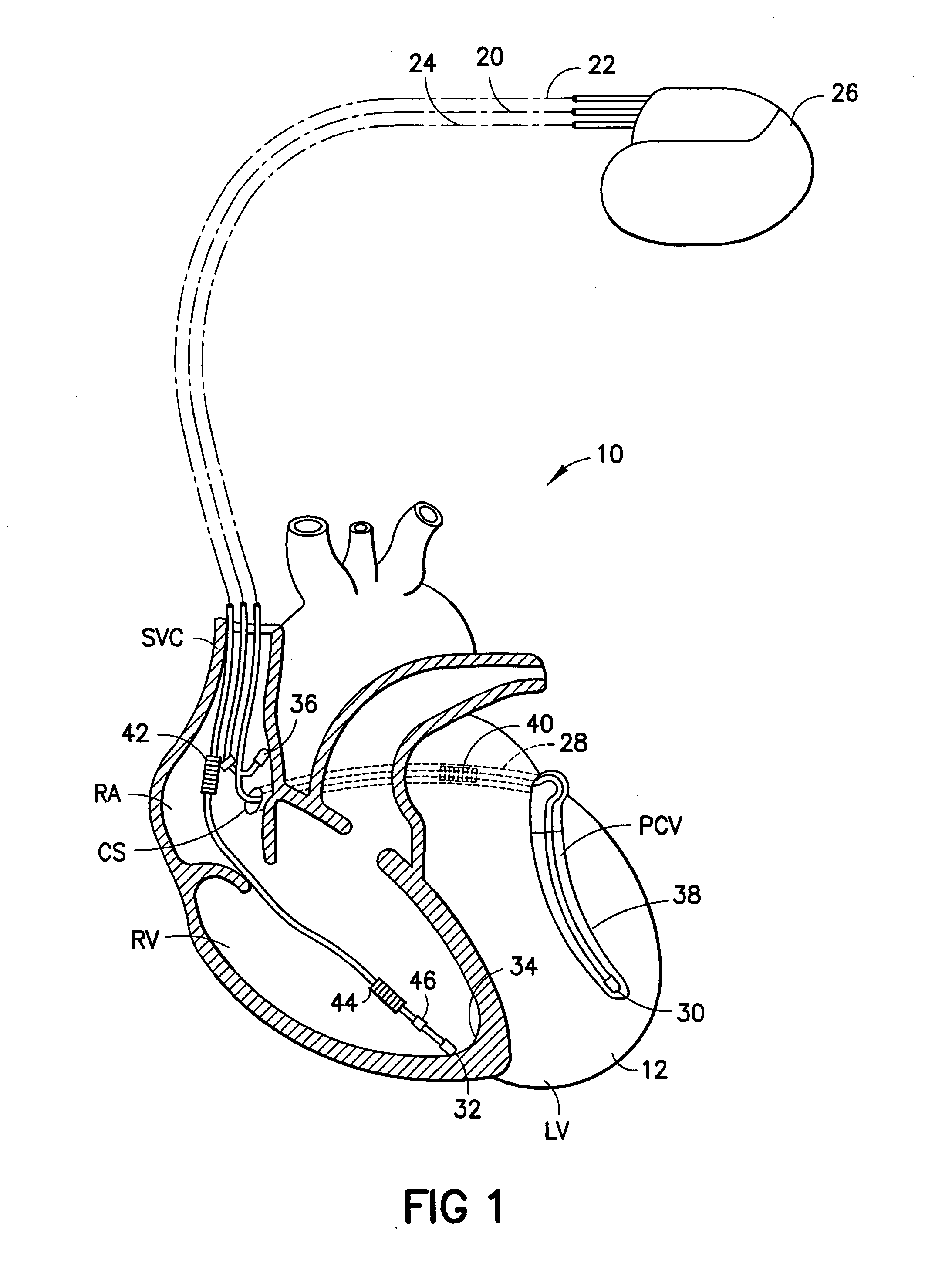
Refer now to the drawings and, initially, to FIG. 1 in which is shown a diagrammatic perspective view of an implanted system 10 for providing electrical stimulation of a heart 12 incorporating features of the present invention. Although the present invention will be described with reference to the embodiments shown in the drawings, it should be understood that the present invention can be embodied in many alternate forms or embodiments. In addition, any suitable size, shape or type of elements or materials could be used.

In FIG. 1, implantable leads 20, 22, 24 are illustrated generally embodying the invention for stimulation of the body, the heart 12 in this instance, by means of a pacemaker 26 or other suitable pulse generating or stimulating device. This is a cross section view of a human heart showing the right atrium RA and the right ventricle RV along with the coronary sinus CS and a vein 28 of the left side of the heart. This vein of the left side could be any of the veins f...


PUM


Abstract

An implantable cardiac stimulation lead system for use with a stimulation device includes a lead body preferably having an outer diameter of less than 4 French and formed of a biocompatible material having a Young's modulus of at least 20,000 pounds per square inch. In the lead body, an inner insulator is composed of a suitable polymer such as PTFE or ETFE with an outer peripheral surface formed with a helical groove containing a conductor extending between a proximal connector and a distal tip electrode, and an outer insulator composed of polyurethane or silicone rubber or a combination thereof is positioned around the inner insulator. The lead system may be formed with a lumen for receiving a guidewire longitudinally through the lead body. A pair of insulated conductors may be received in the helical groove, one extending to the distal tip electrode, the other extending to a ring electrode proximally spaced from the distal tip electrode.

Description

FIELD OF THE INVENTION The present invention relates generally to implantable medical devices for providing stimulating pulses to selected body tissue, and more particularly, to the construction of lead assemblies in which the lead body diameter is minimized. Further, the present invention relates generally to implantable cardiac leads, and more particularly to endocardial leads having relatively small diameter lead bodies. BACKGROUND OF THE INVENTION Over the past few years, there has been a substantial effort to reduce the diameter of endocardial pacing, cardioversion and defibrillation leads. Reduction in lead body diameter facilitates placement of multiple leads through a single blood vessel and also minimizes interference between the lead body and the tricuspid valve, in the case of leads implanted in the right ventricle. In addition, a reduction in lead body size has generally been accompanied by a reduction in the lead body's flexural stiffness or bending moment. This reduc...

Claims


Application Information

Patent Timeline
Patent Type & Authority Applications(United States)
IPC IPC(8): A61N1/05
CPCA61N1/056
Inventor CHITRE, YOUGANDHBORNZIN, GENE A.WILLIAMS, SHELDON
Owner PACESETTER INC
Why Eureka
Try Eureka