Electronic control unit

US20050080529A1Active Publication Date: 2005-04-14MITSUBISHI ELECTRIC CORP

Image

  • Electronic control unit
  • Electronic control unit
  • Electronic control unit

Examples


embodiment 1

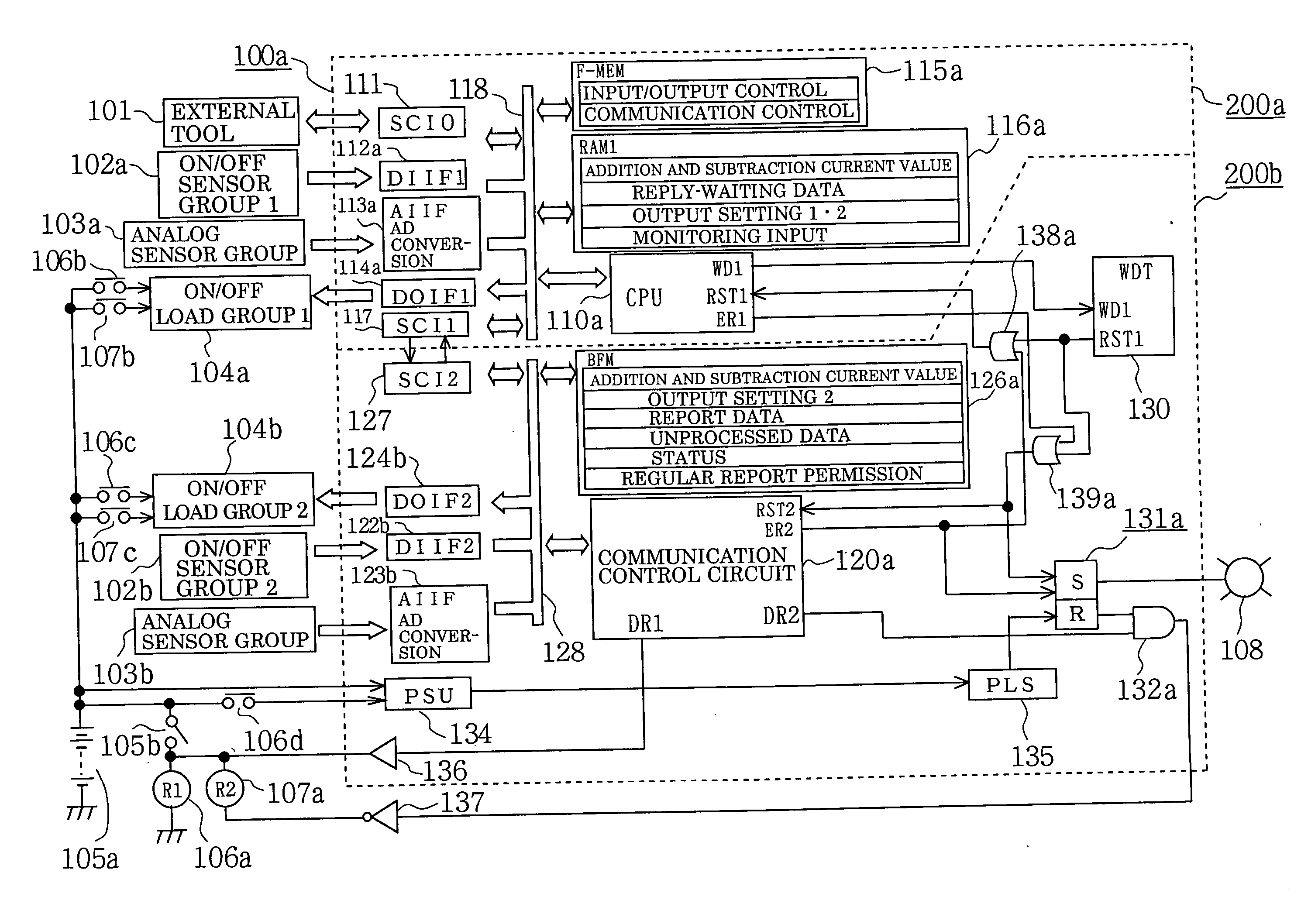
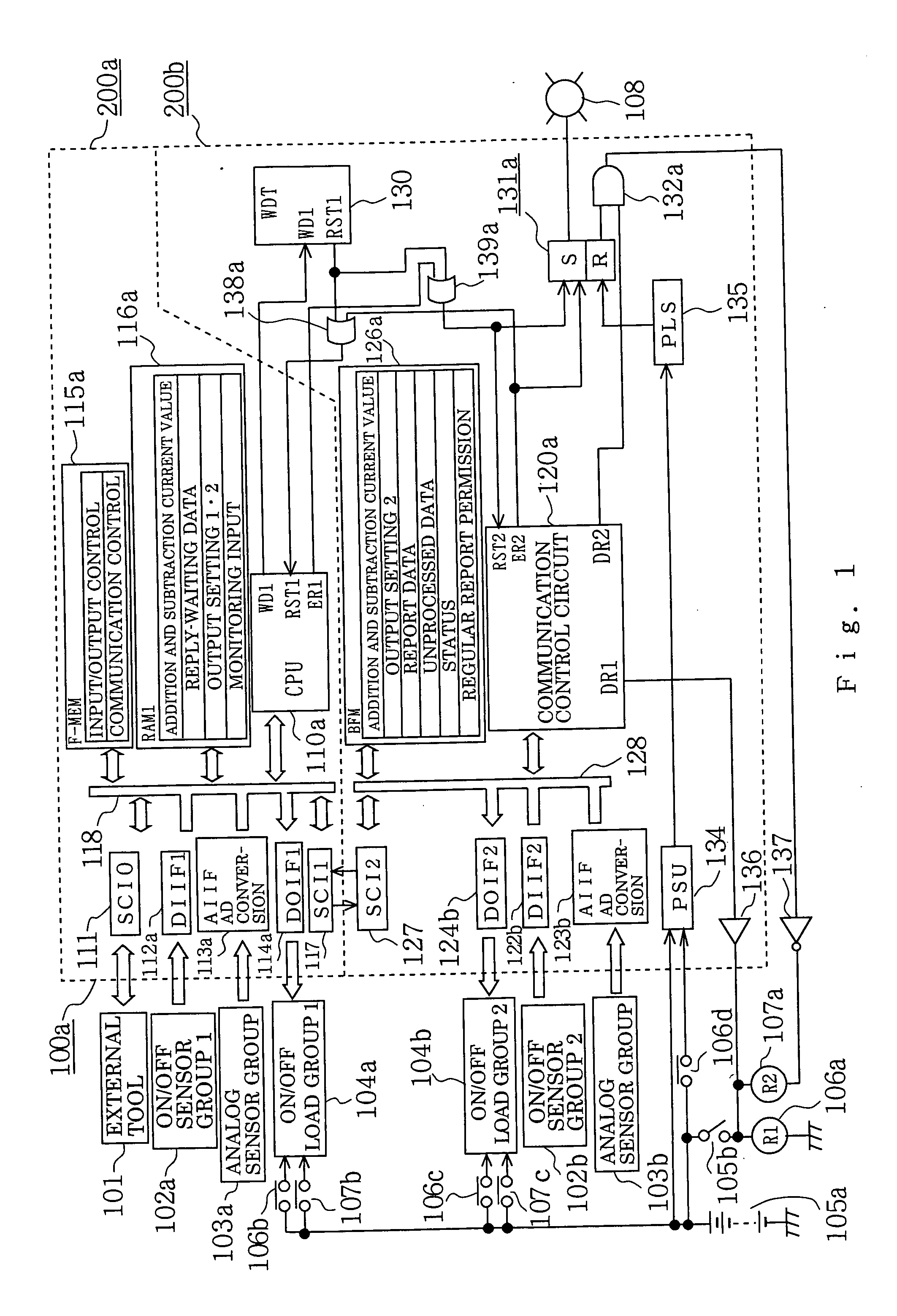
[0045]FIG. 1 is a block diagram showing an entire constitution of an electronic control unit according to a first embodiment.

[0046] With reference to FIG. 1, reference numeral 100a designates an electronic control unit consisting of a first control circuit section 200a and a second control circuit section 200b.

[0047] First, components connected to the outside of the mentioned electronic control unit 100a are described.

[0048] Numeral 101 designates an external tool. This external tool is connected via a detachable connector, not shown, to the mentioned electronic control unit 100a at the time of delivering a product or carrying out a maintenance inspection, and functions to transfer and write a control program or a control constant to the later-described non-volatile program memory 115a.

[0049] Numeral 102a designates a first input sensor group that performs an ON / OFF operation (for example, an engine speed sensor, a crank angle sensor, and a speed sensor). This first input sensor...

embodiment 2

[0214]FIG. 8 is a block diagram showing an entire constitution of an electronic control unit according to a second preferred embodiment of the invention.

[0215] In the electronic control unit according to the foregoing first embodiment, the communication control circuit section 120a is constituted of an integrated circuit element employing a logical circuit. Whereas, the electronic control unit according to this second embodiment differs from that of the first embodiment mainly in the aspects that an auxiliary CPU 120b is provided to act as a communication control circuit section, and that irregular transmission means is added to the first control circuit section.

[0216] Hereinafter, the electronic control unit according to the second embodiment is described focusing on points different from the electronic control unit according to the foregoing first embodiment shown in FIG. 1.

[0217] Now referring to FIG. 8, numeral 100b designates an electronic control unit consisting of a first ...


PUM


Abstract

A first control circuit section (master station) and a second control circuit section (substation) communicate with each other via series-parallel converters. The master station includes regular transmission device and transmission-permitting signal generation device; and the sub station includes regular report device, confirmation reply device relative to a transmission data from the master station, and an unprocessed data table. The unprocessed data table prevents jam-up in upstream communication from the sub station to the master station, enabling to carry out timely regular transmission and regular reporting. Transmission from the sub station to the master station is performed based on a transmission-permitting control signal that the master station generates. Consequently, it is possible to execute communication error processing and diminish communication control burden on the master station while properly performing the regular transmission and regular report between the master station and sub station.

Description

BACKGROUND OF THE INVENTION [0001] 1. Field of the Invention [0002] The present invention relates to an electronic control unit having a microprocessor built-in for use in, for example, a fuel supply control of an automobile engine and, more particularly, to improvement of an on-vehicle electronic control unit including a plurality of control circuit sections electrically divided so as to carry out mutual communication of serial signals. [0003] 2. Description of the Related Art [0004] On-vehicle electronic control unit in which information exchange by a method of serial communication is carried out among a plurality of microprocessors sharing functions, and communication error is detected to carry out error processing, has been practically and widely used in various fields. [0005] For example, according to the Japanese Patent Publication (unexamined) No. 108835 / 2002, the following “On-Vehicle Electronic Control Unit” is proposed. This on-vehicle electronic control unit comprises ser...

Claims


Application Information

Patent Timeline
14 Apr 2005
Publication
US20050080529A1
IPC
F02D45/00; G05B19/05; G06F11/00; G06F11/267; G06F13/00; G06F13/40; H04B7/212
CPC
G06F11/221; G06F11/0757
Inventors
HASHIMOTO, KOHJI; NAKAMOTO, KATSUYA