System and method for data synchronization for a computer architecture for broadband networks

Active Publication Date: 2005-04-14
SONY COMPUTER ENTERTAINMENT INC
View PDF99 Cites 213 Cited by
  • Summary
  • Abstract
  • Description
  • Claims
  • Application Information

AI Technical Summary

Benefits of technology

[0017] In another aspect, the present invention provides a synchronized system and method for an APU's reading of data from, and the writing of data to, the shared DRAM. This system avoids conflicts among the multiple APUs and multiple PEs sharing the DRAM. In accordance with this system and method, an area of the DRAM is designated for storing a plurality of full-empty bits. Each of these full-empty bits corresponds to a designated area of the DRAM. The synchronized system is int

Problems solved by technology

This heterogeneous combination of computers and computing devices on today's computer networks complicates the processing and sharing of data and applications.
The sharing of data and applications among this assortment of computers and computing devices presents substantial problems.
These techniques include, among others, sophisticated interfaces and complicated programming techniques.
These solutions often require substantial increases in processing power to implement.
They also often result in a substantial increase in the time required to process applications and to transmit data over networks.
While this approach minimizes the amount of bandwidth needed, it also often causes frustration among users.
This additional layer of softwa

Method used


Image

  • System and method for data synchronization for a computer architecture for broadband networks
  • System and method for data synchronization for a computer architecture for broadband networks
  • System and method for data synchronization for a computer architecture for broadband networks

Examples


Embodiment Construction

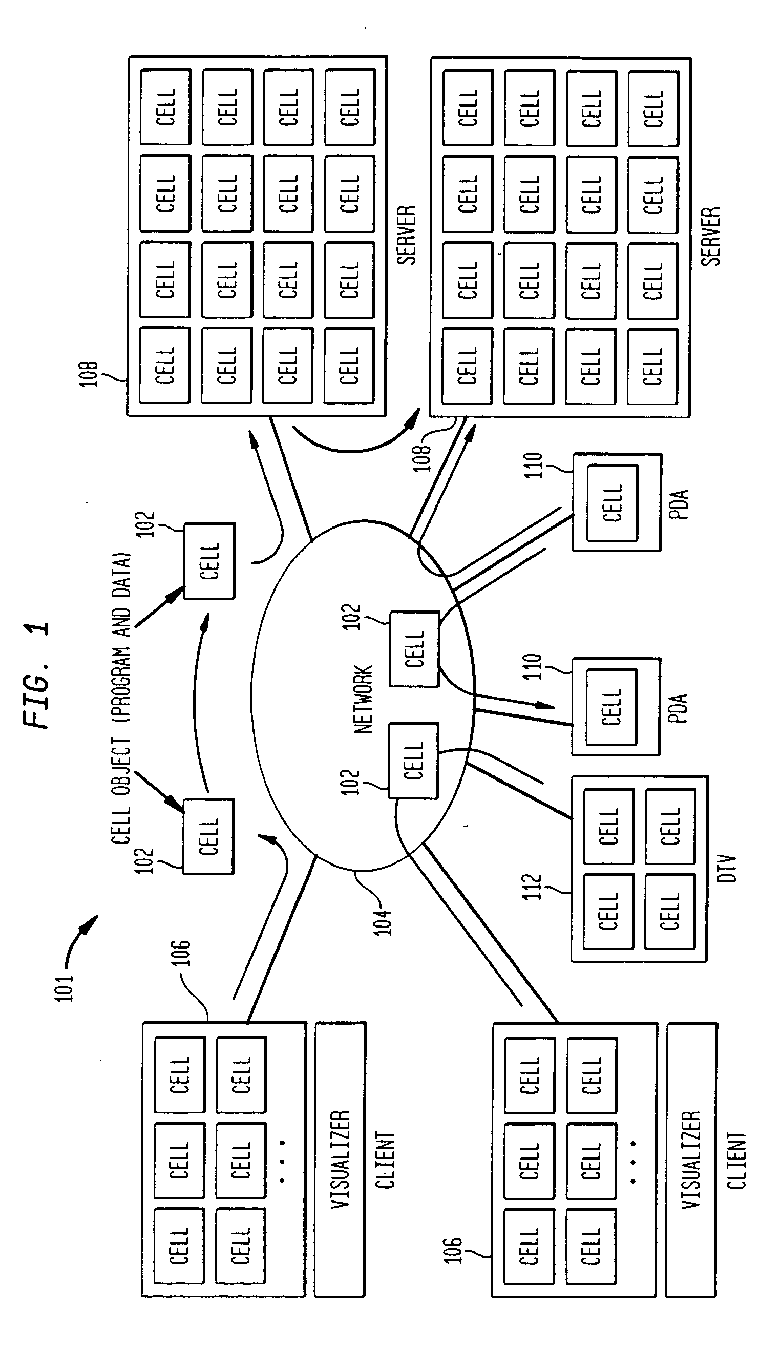
[0057] The overall architecture for a computer system 101 in accordance with the present invention is shown in FIG. 1.

[0058] As illustrated in this figure, system 101 includes network 104 to which is connected a plurality of computers and computing devices. Network 104 can be a LAN, a global network, such as the Internet, or any other computer network.

[0059] The computers and computing devices connected to network 104 (the network's “members”) include, e.g., client computers 106, server computers 108, personal digital assistants (PDAs) 110, digital television (DTV) 112 and other wired or wireless computers and computing devices. The processors employed by the members of network 104 are constructed from the same common computing module. These processors also preferably all have the same ISA and perform processing in accordance with the same instruction set. The number of modules included within any particular processor depends upon the processing power required by that processor.

[...


PUM


Abstract

A computer architecture and programming model for high speed processing over broadband networks are provided. The architecture employs a consistent modular structure, a common computing module and uniform software cells. The common computing module includes a control processor, a plurality of processing units, a plurality of local memories from which the processing units process programs, a direct memory access controller and a shared main memory. A synchronized system and method for the coordinated reading and writing of data to and from the shared main memory by the processing units also are provided. A processing system for processing tasks is also provided. The processing system includes processing devices and an absolute timer. The absolute timer defines a time budget. The time budget provides a time period for the completion of tasks by selected processing devices independent of clock frequencies employed by the processing devices for processing the tasks.

Description

CROSS-REFERENCE TO RELATED APPLICATIONS [0001] This application is a continuation of application Ser. No. 09 / 815,554, filed Mar. 22, 2001, entitled SYSTEM AND METHOD FOR DATA SYNCHRONIZATION FOR A COMPUTER ARCHITECTURE FOR BROADBAND NETWORKS. This application is also a continuation of application Ser. No. 10 / 371,322, filed Feb. 21, 2003, entitled MEMORY PROTECTION SYSTEM AND METHOD FOR COMPUTER ARCHITECTURE FOR BROADBAND NETWORKS, which is a continuation of application Ser. No. 09 / 816,020, filed Mar. 22, 2001, now U.S. Pat. No. 6,526,491, entitled MEMORY PROTECTION SYSTEM AND METHOD FOR COMPUTER ARCHITECTURE FOR BROADBAND NETWORKS, the entire disclosures of which are hereby expressly incorporated by reference.BACKGROUND OF THE INVENTION [0002] The present invention relates to an architecture for computer processors and computer networks and, in particular, to an architecture for computer processors and computer networks in a broadband environment. The present invention further relat...

Claims


Application Information

Patent Timeline
IPC IPC(8): G06F12/14G06F15/16G06F15/80G06F21/62H04L29/06
CPCH04L69/12G06F12/1466G06F12/14
Inventor SUZUOKI, MASAKAZUYAMAZAKI, TAKESHI
Owner SONY COMPUTER ENTERTAINMENT INC
Why Eureka
Try Eureka