

Bi-directional fabric and fabric composites
a technology of fabric composites and bi-directional fabrics, applied in the direction of protective fabrics, straight-bar knitting machines, synthetic resin layered products, etc., can solve the problems of poorer ballistic resistance of woven or knitted fabrics than cross-plied, and achieve superior ballistic effectiveness, superior penetration resistance, and reduced cost and ease of manufacture.
- Summary
- Abstract
- Description
- Claims
- Application Information
AI Technical Summary
Benefits of technology
Problems solved by technology
Method used
Image

Examples
example 1
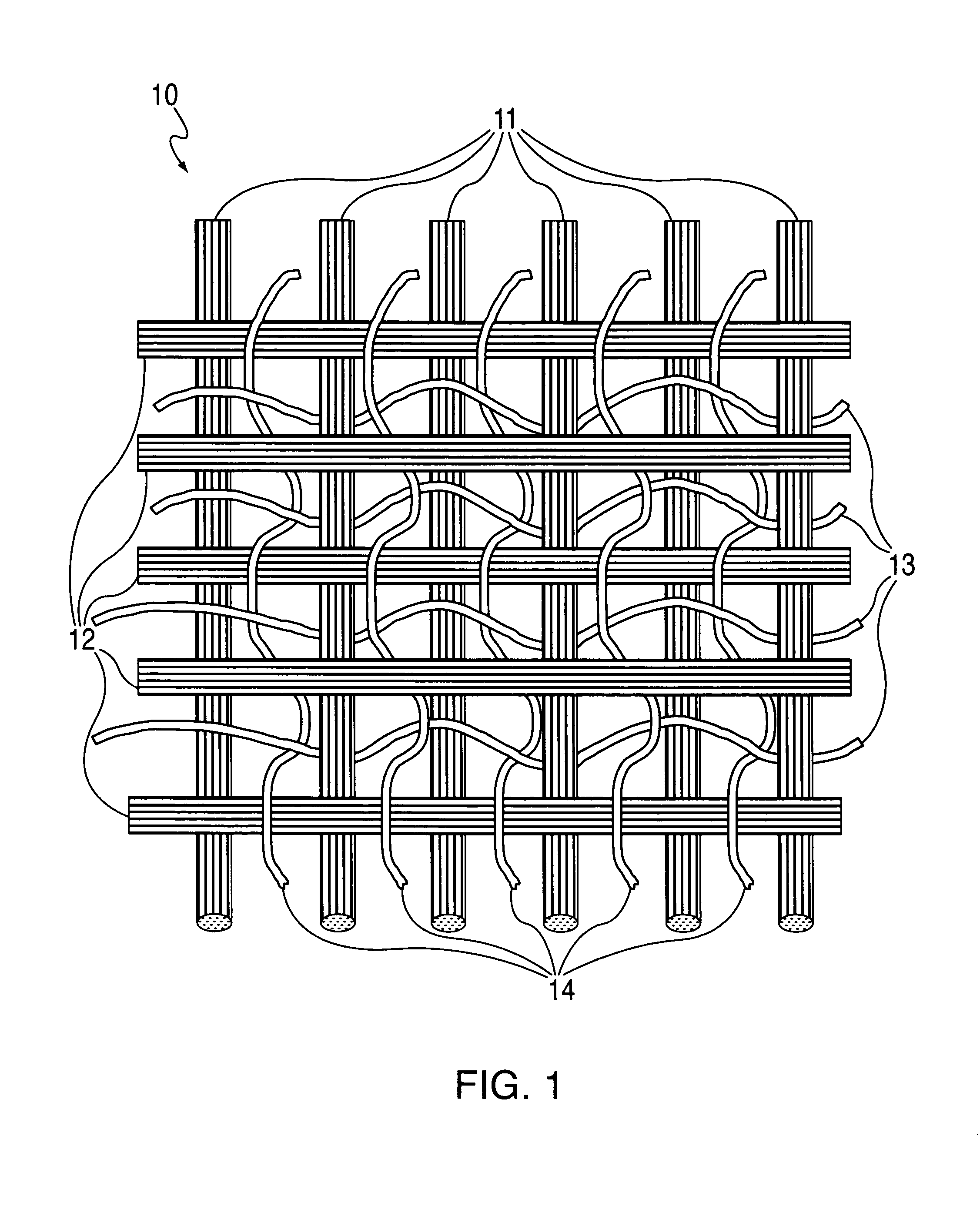
[0072] A bi-directional fabric of the invention was woven on an American Iwer Model A2 180 loom. The fabric consisted of four yarn sets. The first yarn and second yarn sets each consisted of parallel highly oriented, high molecular weight polyethylene yarns (SPECTRA®1000 from Honeywell International Inc.) of 1300 denier and having a tenacity of 35 g / d, initial tensile modulus of 1150 g / d, energy-to-break of 45 J / g, breaking strength of 45 Kg and 3.4% elongation at break. Referring to the schematic representation of FIG. 1, the first yarn set 11 and the second yarn set 12 were unidirectionally oriented transverse to one another in separate planes, one above the other. A third yarn set 13 arranged transversely to the first yarn set 11 and interlaced with the yarns of the first set consisted of polyvinyl alcohol yarns of 75 denier and having a breaking strength of 0.38 Kg and 20% elongation at break. A fourth yarn set 14 arranged transversely to the second and third yarn sets and inter...
example 2
[0074] A second set of thirty-four 12″×12″ (30.5 cm×30.5 cm) sheets of the same bi-directional fabric prepreg prepared in Example 1 were cut and stacked together. The sheets were bonded and cured into a unitary fabric composite panel by heating in a press at 116° C. under a pressure of 550 psi (3.8 MPa) for 20 minutes. The areal density of the second bi-directional fabric composite panel was 1.03 lbs / sq. ft. (5.03 Kg / sq. m).
example 3
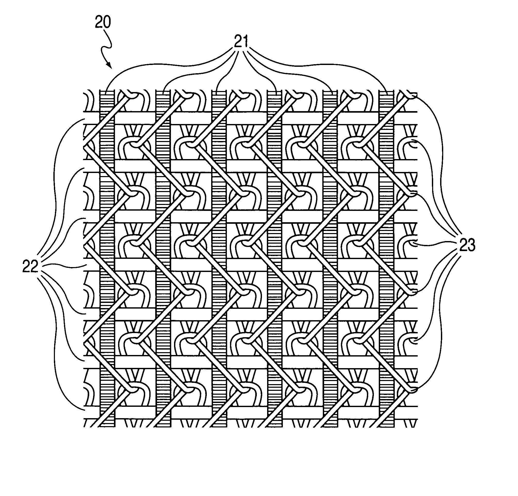
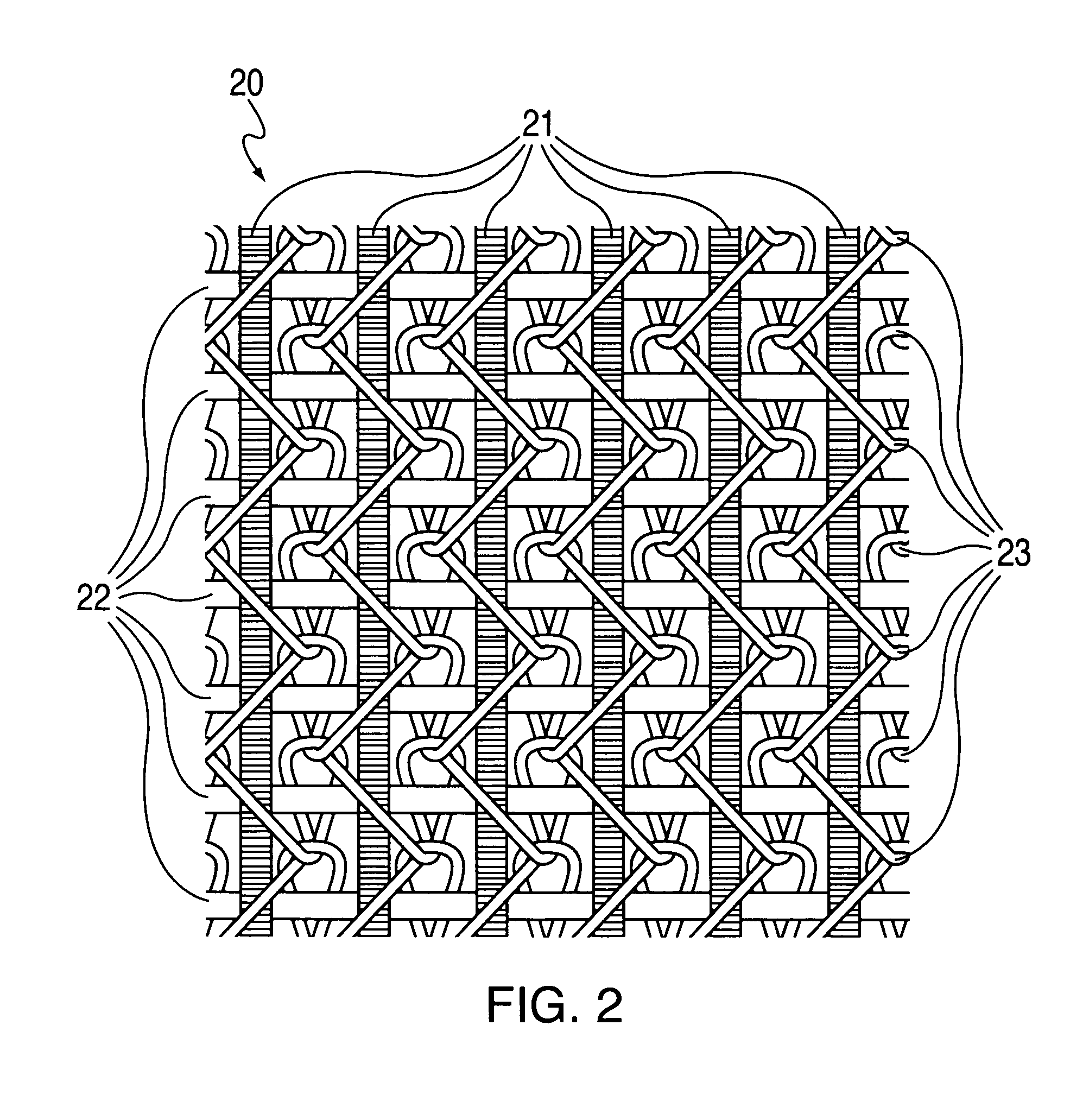
[0075] A bi-directional fabric of the invention was knitted on a weft inserted, warp knit machine from Liba, Inc. The fabric consisted of three yarn sets. The first yarn and second yarn sets each consisted of highly oriented high molecular weight polyethylene yarns (SPECTRA® 1000 from Honeywell International Inc.) of 1300 denier and having a tenacity of 35 g / d, initial tensile modulus of 1150 g / d, energy-to-break of 45 J / g, breaking strength of 45 Kg and 3.4% elongation at break. Referring to the schematic representation of FIG. 2, the first yarn set 21 and the second yarn set 22 were unidirectionally oriented transverse to one another in separate planes, one above the other.
[0076] The spacing of yarns in each of the first and second yarn sets in the fabric was 9 ends / in (3.5 ends / cm). A third yarn set 23 consisting of polyvinyl alcohol of 75 denier and having 0.38 Kg breaking strength, 22% elongation at break was interleaved with both the first and second yarn sets with a tricot s...
PUM
| Property | Measurement | Unit |
|---|---|---|
| melting points | aaaaa | aaaaa |
| melting points | aaaaa | aaaaa |
| temperature | aaaaa | aaaaa |
Abstract
Description
Claims
Application Information