High-sensitivity pressure conduction sensor for localized pressures and stresses

a pressure conduction sensor, high-sensitivity technology, applied in the direction of mechanical measurement arrangement, instruments, using mechanical means, etc., can solve the problems of affecting the dynamic range of instruments, affecting the pressure detection, and easy to be contaminated by dirt, moisture and other contaminants, etc., to achieve more accurate and detailed measurements, more sensitive, and easy to use

Active Publication Date: 2005-04-21
QORTEK
View PDF4 Cites 18 Cited by
  • Summary
  • Abstract
  • Description
  • Claims
  • Application Information

AI Technical Summary

Benefits of technology

[0027] The described invention provides several advantages over the related arts. The invention is inherently more sensitive resulting in more accurate and detailed measurements. The noise component within the usable signal from the present inv

Problems solved by technology

Keys are susceptible to dirt, moisture, and other contaminants.
Mechanical solutions adversely effect pressure detection and penalize the dynamic range of the instrument.
Devices are difficult to conceal and readily defeatable.
Furthermore, such systems are limited in their mapping capability and therefore do not provide a complete record of an intrusion, including, but not limited to, location and time, to resolve direction of travel and speed.
However, such systems must function within a harsh environment including rapidly changing pressures.
Diaphragm-based gages offer reliable pressure measurement, even when surrounded by corrosive and high temperature fluids, but are generally t

Method used


Image

  • High-sensitivity pressure conduction sensor for localized pressures and stresses
  • High-sensitivity pressure conduction sensor for localized pressures and stresses
  • High-sensitivity pressure conduction sensor for localized pressures and stresses

Examples


Embodiment Construction

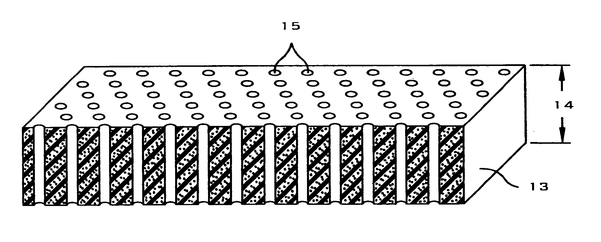
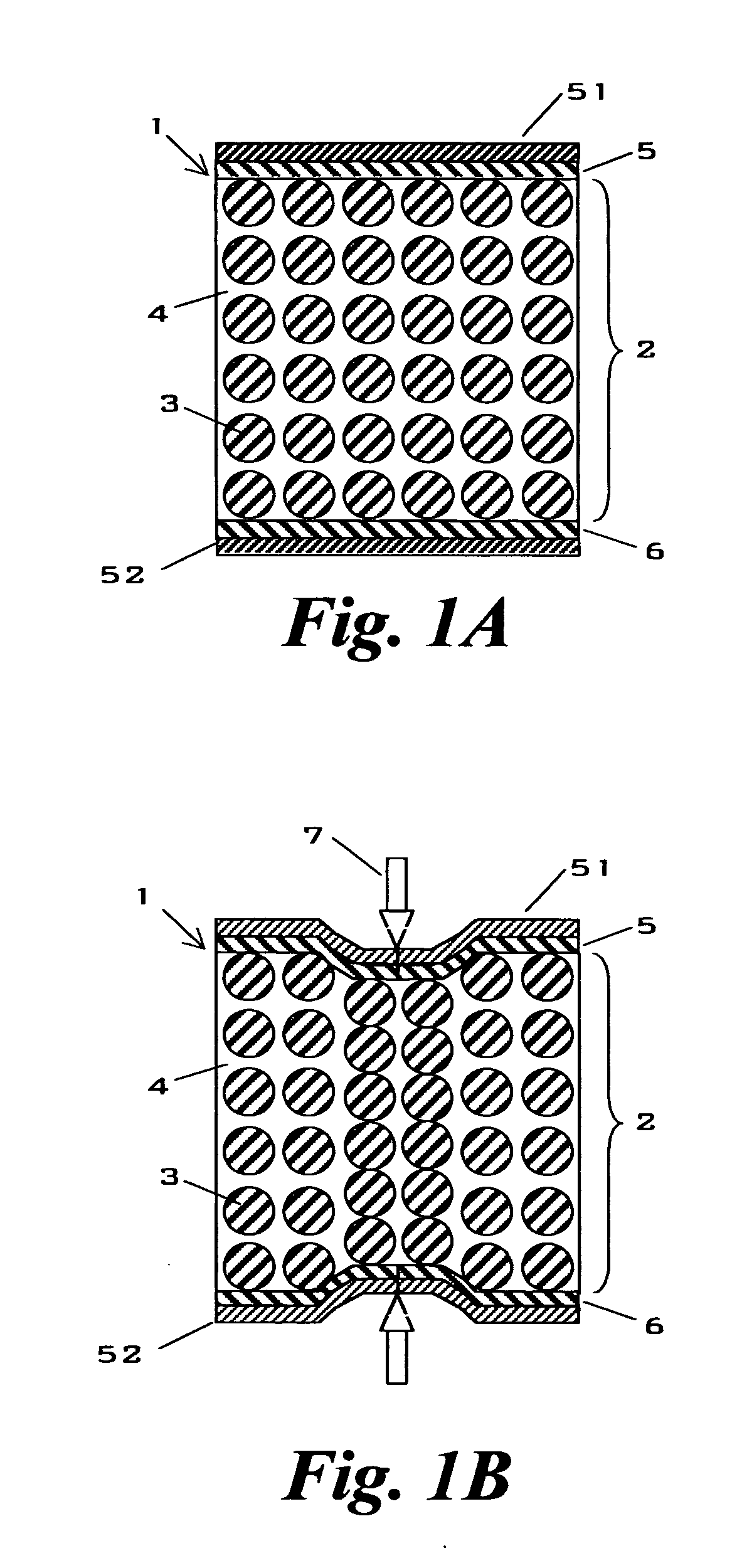
[0088] Referring now to FIG. 1a, a schematic representation of one embodiment of the sensor 1 is shown having a pressure conduction composite 2 disposed between two conductive layers 5, 6. An optional pair of non-conductive layers 51 and 52 contact the conductive layers 5 and 6, respectively, opposite of the pressure conduction composite 2.

[0089] Conductive layers 5, 6 include a variety of materials, such as metals and composites, and a variety of generally planar structures, including plates, foils, films, foams, weaves, and braids. The pressure conduction composite 2 is composed of conductive particles 3 within a non-conductive yet pliable and resilient matrix 4. The matrix 4 is a generally planar solid that surrounds and isolates the conductive particles 3 so as to maximize resistance and minimize conductance thereby preventing current flow between conductive layers 5, 6 at an ambient or biased pressure. Non-conductive layers 51, 52 isolate the sensor 1 so as to prevent electric...


PUM


Abstract

A high-sensitivity pressure conduction sensor is presented. The present invention includes a pair of locally resilient conductive layers and a locally resilient pressure conduction composite disposed between and contacting both conductive layers. Alternate embodiments include at least three locally resilient conductive layers and at least two locally resilient pressure conduction composites, each having a critical percolation threshold. Each composite is disposed between and contacting two conductive layers in a multi-layer fashion. Other embodiments include a locally resilient pressure conduction composite, a flexible substrate completely surrounding the composite so as to seal it therein, and a pair of electrical leads contacting the composite and terminating outside of the flexible substrate. Pressure conduction composites are composed of a plurality of conductive particles electrically isolated within a non-conductive matrix. Conductive particles are loaded so as to have a volume fraction approaching the critical percolation threshold of the material system and exhibit a conductance that greatly increases with pressure. Sensors may be arranged to form one or more arrays including planar and conformal configurations. The present invention has immediate application in keyboards, intrusion systems, control systems, submarines, ships, sonobuoys, doors, and switches.

Description

CROSS REFERENCE TO RELATED APPLICATIONS [0001] This application is based upon and claims priority under 35 U.S.C. § 119(e) from U.S. Provisional Patent Application No. 60 / 512,335 filed Oct. 17, 2003, entitled Pressure Conduction Devices, the contents of which are hereby incorporated by reference.FEDERALLY SPONSORED RESEARCH AND DEVELOPMENT [0002] None. BACKGROUND OF THE INVENTION [0003] 1. Field of the Invention [0004] The present invention generally relates to a device capable of large conduction changes when locally compressed and decompressed. Specifically, the present invention is a sensor of sufficiently high sensitivity so as to enable pressure and stress measurements. [0005] 2. Description of the Related Art [0006] Sensors are critical to the performance of keyboards, intrusion detection systems, and fluid control systems. [0007] Musical keyboards employ carbon contacts to detect the depression of a key and a capacitive strip to measure how hard and fast the key is depressed ...

Claims


Application Information

Patent Timeline
IPC IPC(8): G01N3/06G01N3/12
CPCG01N2203/0617G01N3/12
Inventor KNOWLES, GARETHHUGHES, ELI
Owner QORTEK
Why Eureka
Try Eureka