Heald shaft of composite construction

a composite construction and heald shaft technology, applied in the direction of engine seals, textiles and papermaking, weaving, etc., can solve the problems of affecting the uniformity of adhesive gaps, the occurrence of overlapping shaft rods, and the significant contribution of shaft rod oscillation to the noise generation and wear of weaving machines, so as to facilitate the manufacture of uniform adhesive gaps, facilitate the effect of uniform adhesive gaps and good force transmission

Inactive Publication Date: 2005-04-21
GROZ BECKERT KG
View PDF13 Cites 12 Cited by
  • Summary
  • Abstract
  • Description
  • Claims
  • Application Information

AI Technical Summary

Benefits of technology

[0018] By providing for a lateral introduction of the stiffening body into the respective hollow space, the stiffening body may be introduced in a short path into the respective chamber of the shaft rod substantially simultaneously along its entire length. This circumstance significantly facilitates the manufacture of uniform adhesive gaps as compared to an axial introduction of a stiffening body into a hollow space. As a result, a high-quality adhesive bond is made possible which, in turn, ensures a good force transmission between the stiffening body and the light-me...

Problems solved by technology

This applies generally, but it may lead to particular problems in case of long shafts (wide fabrics).
The stresses may cause premature heald breakage, shaft breakage or other defects.
The tendency of the shaft rods to oscillate significantly contributes to the noise generation and wear of the weaving machines.
This requirement constitutes a sig...

Method used


Image

  • Heald shaft of composite construction
  • Heald shaft of composite construction
  • Heald shaft of composite construction

Examples


Embodiment Construction

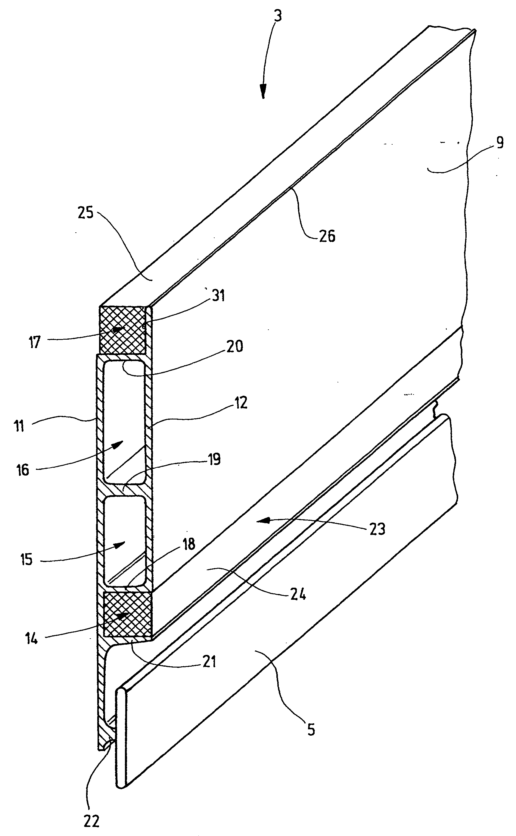
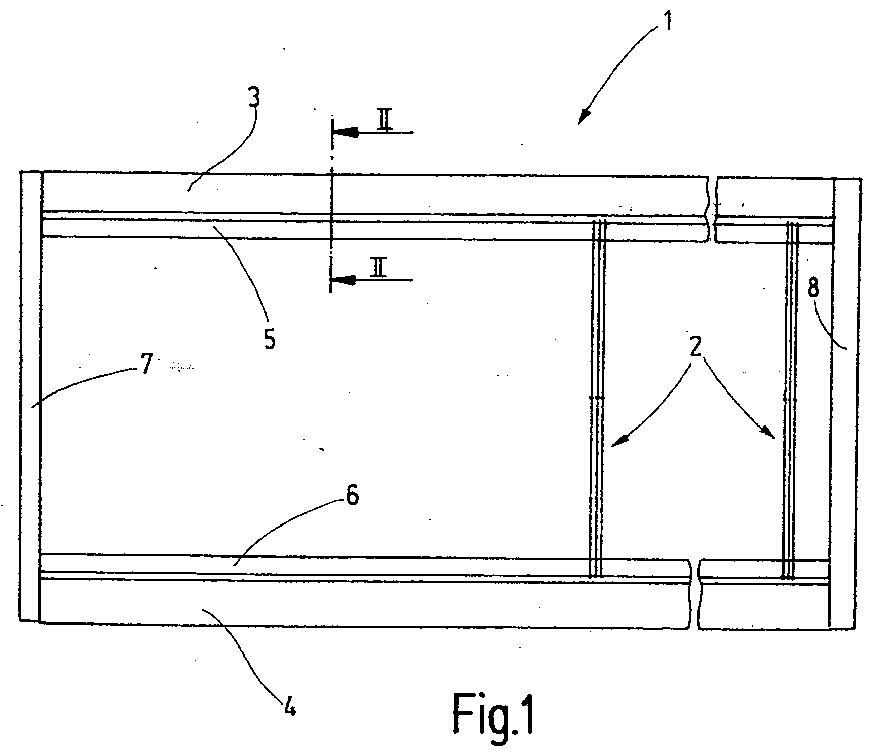
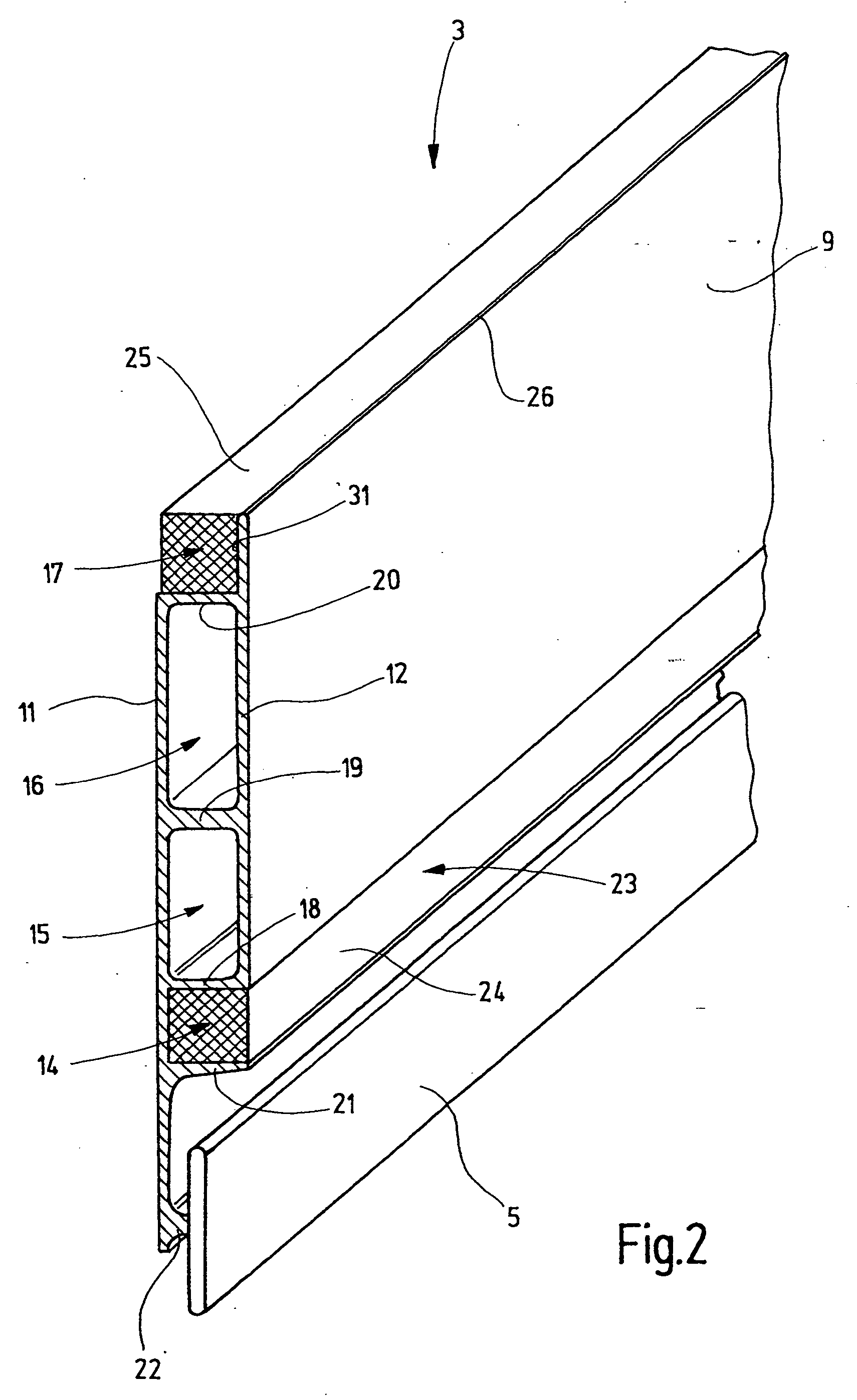
[0030]FIG. 1 illustrates a heald shaft 1 which, together with its healds 2, guides warp threads in a weaving machine (not shown) out of a warp yarn plane upward or downward to present a shed for introducing weft yarns. The heald shaft comprises an upper and a lower shaft rod 3 and 4, respectively, which are each provided with a respective shaft stave 5, 6. The healds 2 are held on the shaft staves 5, 6 by their respective terminal eyelets with a slight vertical play. The shaft rods 3 and 4 which may be of identical construction, are connected to one another at their ends by end binders 7, 8. The following description of different embodiments of the shaft rod 3 therefore equally applies to the shaft rod 4.

[0031] The shaft rod 3 which is separately shown in FIG. 2, has an elongated base body 9 formed of a hollow profile body which may be, for example, a one-piece light-metal body, such as a profiled aluminum component made by extrusion molding. The base body 9 has two substantially p...


PUM


Abstract

A heald shaft for weaving machine has a shaft rod (3) which is formed of a one-piece light-metal profile and two stiffening bodies (24, 25) glued to the shaft rod (3). The stiffening bodies bridge the entire width of the shaft rod (3), wherein the width is measured between the side walls (11, 12). The chambers 14, 16 for receiving the stiffening bodies (24, 25) each have at least one open side through which the stiffening body is visible from the outside and through which it may be introduced into the respective chamber (14, 16). This construction facilitates manufacture. Further, a rigidity in the working direction, as well as a good rigidity transversely thereto is achieved.

Description

CROSS REFERENCE TO RELATED APPLICATION [0001] This application claims the priority of German Patent Application No. 103 49 382.4, filed on Oct. 21, 2003, the subject matter of which, in its entirety, is incorporated herein by reference. FIELD OF THE INVENTION [0002] The invention relates to a heald shaft for weaving machines, particularly for rapidly operating weaving machines. BACKGROUND OF THE INVENTION [0003] The shafts of weaving machines are moved very rapidly during weaving and are induced to oscillate. This applies generally, but it may lead to particular problems in case of long shafts (wide fabrics). The shaft oscillations are generated both parallel and transversely to the longitudinal direction of their motion. The oscillations lead to stresses on the heald shaft, the healds, the heald staves and the warp treads. The stresses may cause premature heald breakage, shaft breakage or other defects. [0004] It has already been repeatedly attempted, on the one hand, to reduce the...

Claims


Application Information

Patent Timeline
IPC IPC(8): D03C9/06F16J15/32
CPCD03C9/0691D03C9/0625
Inventor SCHMID, THOMASBINDER, BERNDBRUSKE, JOHANNES
Owner GROZ BECKERT KG
Why Eureka
Try Eureka