[0009] The method of this invention then includes generating a
signal from the external metrology device to a computer and the computer then uses the data received from the metrology device to determine the position and orientation of the laser
projector relative to the target surface. The metrology receivers may be connected to the computer or the data from the metrology receivers may be transmitted to the computer by a
wireless system. The method of this invention then includes orienting a laser from the laser projector or projectors relative to the target surface to a project laser template on the target surface at a predetermined or defined location and orientation using the data from the computer and finally projecting the laser template on the target surface at the predetermined location and orientation with the laser projector. The method of projecting a laser template on a target surface of this invention thus eliminates the requirement for laser targets on or adjacent the target surface and calibration of the laser projector relative to laser targets on or adjacent the target surface and is thus “targetless.” Further, the metrology receivers do not have to be within a
field of view of the laser projector or projectors.
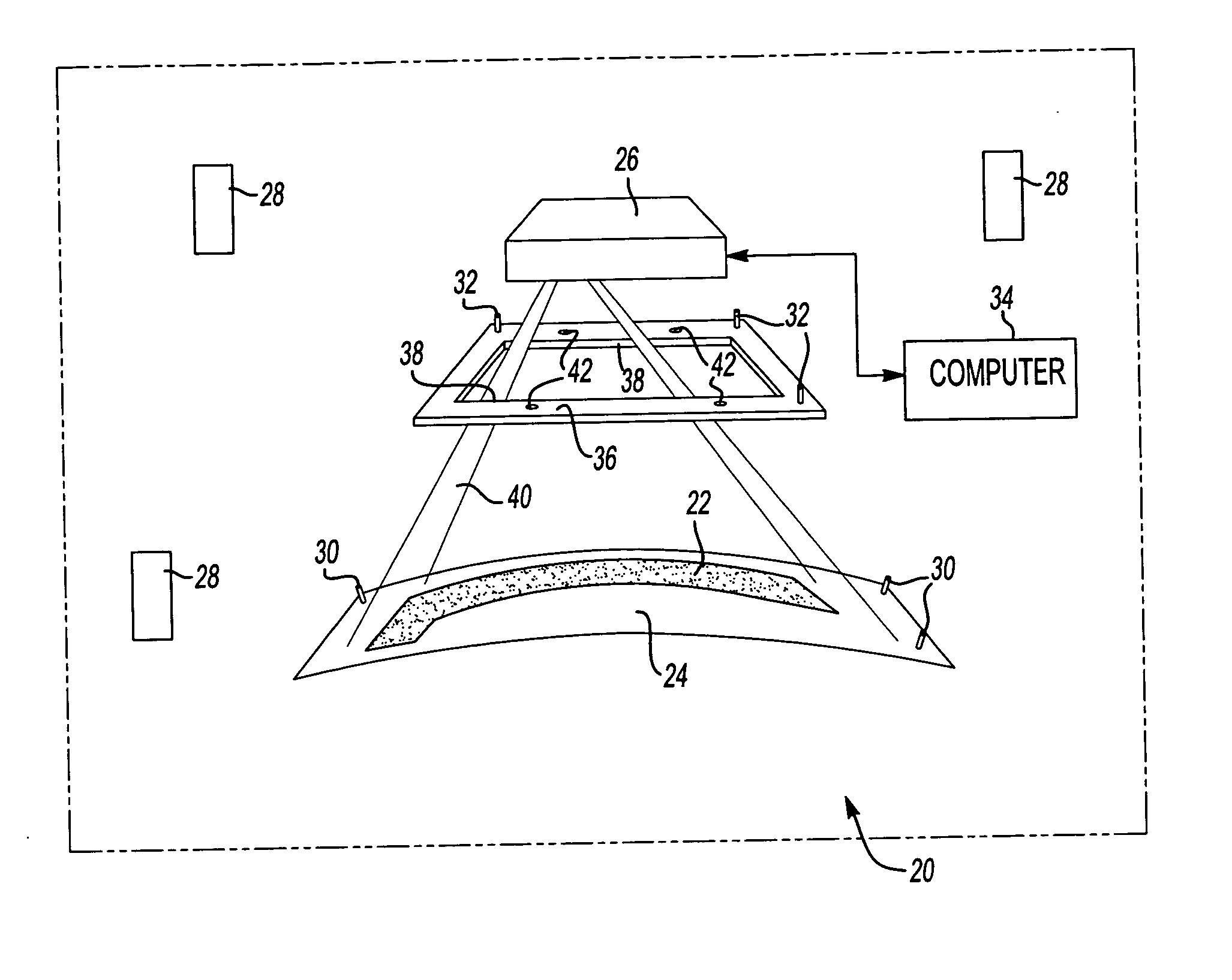
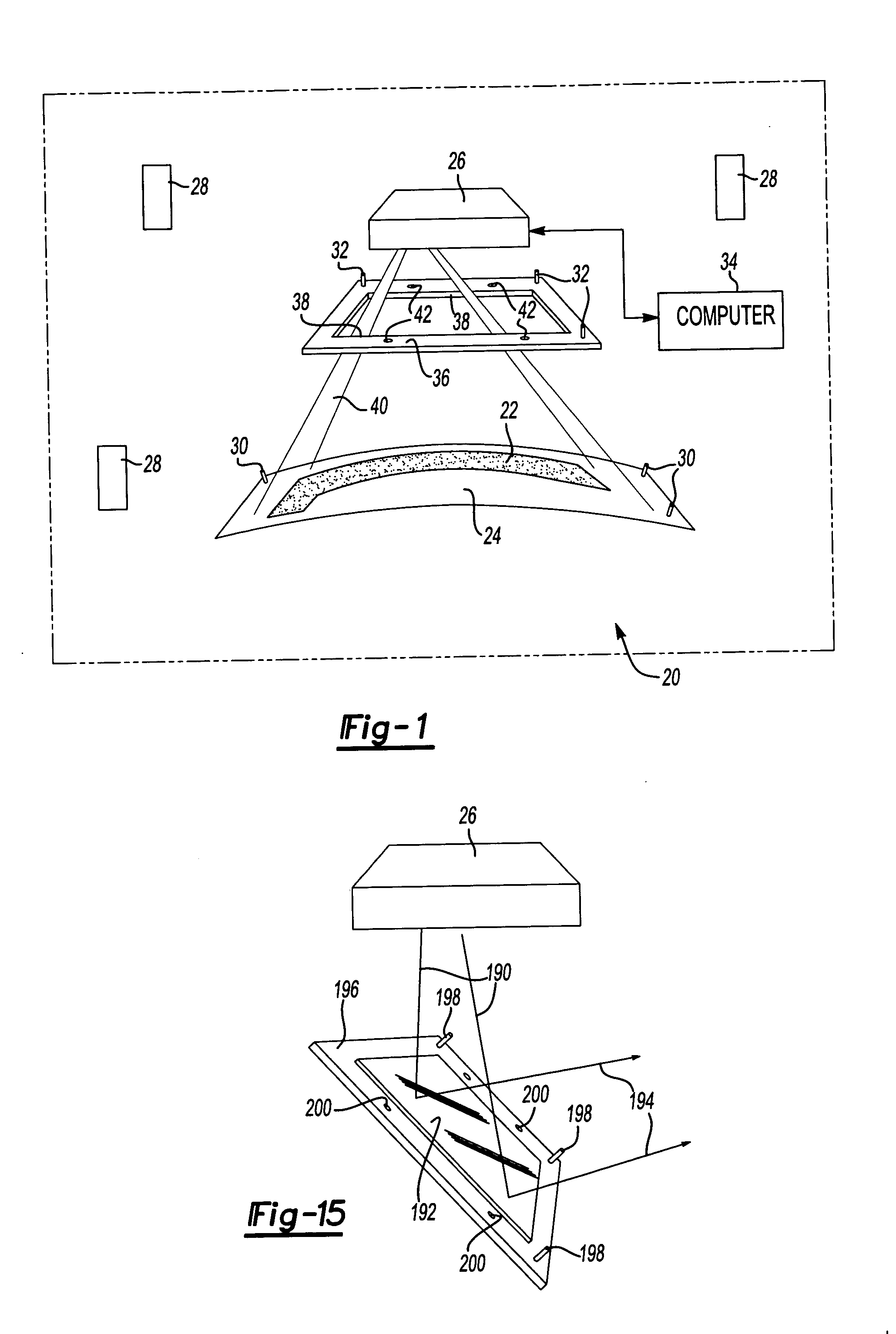
[0011] In one preferred embodiment of the frame
assembly of this invention disclosed herein, the frame includes a
support surface and a distal open end. The laser projector is rigidly supported on the
support surface of the frame
assembly and the method of this invention then includes projecting the laser template through the distal open end of the frame assembly. The metrology receivers in the disclosed embodiment of the frame assembly are attached at predetermined locations to the distal open end of the frame assembly for accurately determining the position and orientation of the laser targets and thus the laser projector by the method of this invention. Further, in the disclosed embodiment of the frame assembly, the laser targets are also located on the distal open end of the frame assembly opposite the laser projector. The method of this invention then includes periodically scanning the laser targets on the distal open end of the frame assembly and correcting for laser image drift or movement of the laser projector. However, where the metrology receivers are fixed relative to the laser targets, the laser projector may move relative to the frame and determine its position and orientation by scanning the laser targets. As used herein, the term “periodically” includes continuously scanning the laser targets and the laser targets may be retroreflective targets or any suitable
laser target or
position sensor, as disclosed for example in the above referenced U.S. Pat. No. 5,646,859.
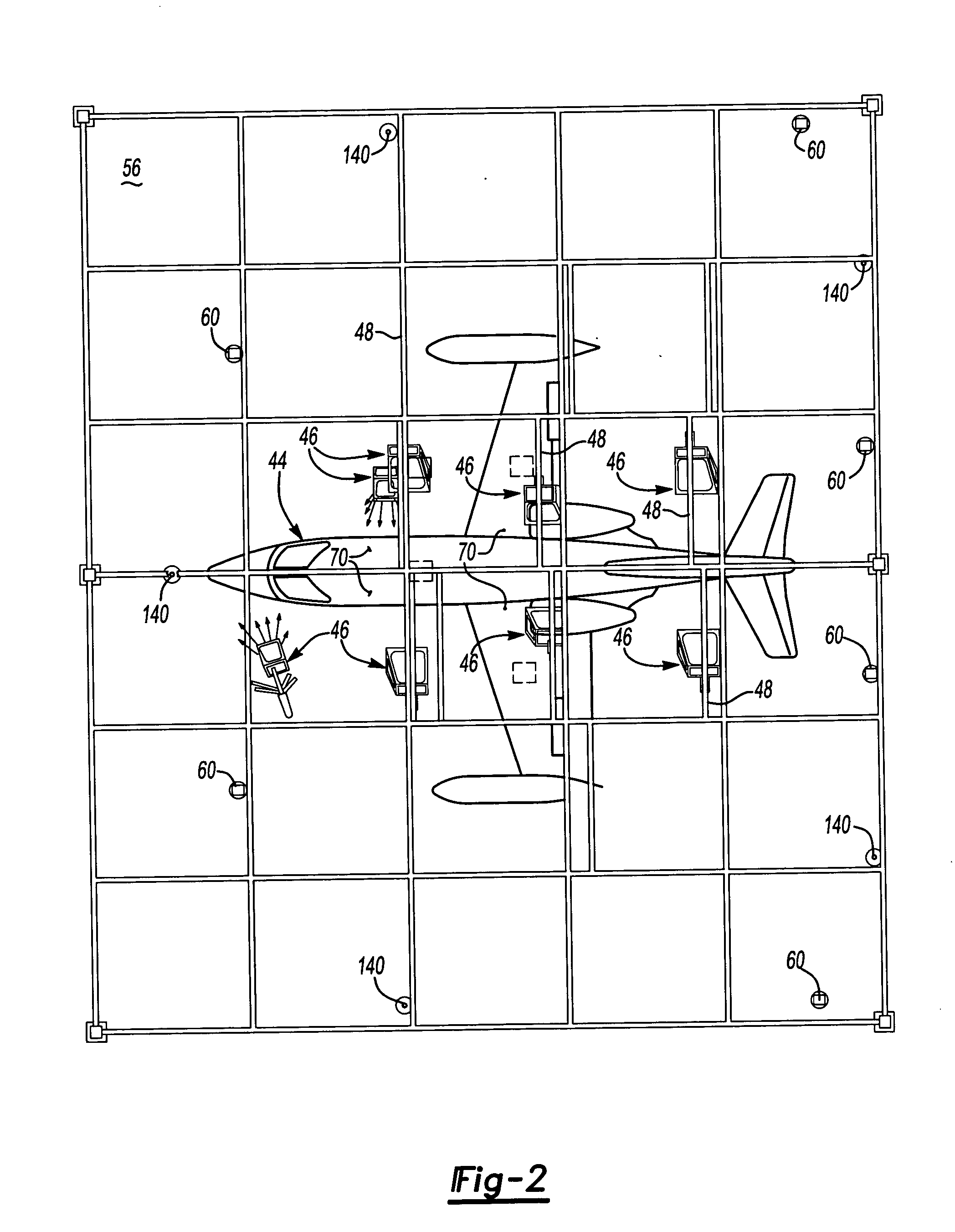
[0014] As set forth above, the laser
projection system and method of this invention is particularly, but not exclusively suitable for projecting a laser template on a target surface, where laser targets would interfere with subsequent operations, such as ply layup on
large target surfaces, such as an aircraft body, for subsequent operations, such as the application of decals, placement of fixtures and covering the joints between the components of the target surface, such as an aircraft. Of course, however, the laser
projection system and method of this invention is not limited to any particular application. In such applications, however, it is desirable to fix the metrology receivers or reflectors on stanchions, such that the reflector or
receiver is located above the floor for ease of reference in determining the position and orientation of the target surface. In one preferred embodiment of the metrology
receiver assembly of this invention, the
receiver assembly may be removed from the support and replaced without changing the position and orientation of the metrology receiver. In this embodiment, the metrology receiver assembly includes a support stanchion adapted to be permanently affixed to a support in a
workstation in a predetermined location. A bottom kinematic plate is fixed to the top of the support stanchion and the assembly includes a receiver support member having a top kinematic plate secured to the support member releasably attached to the bottom kinematic plate. In a preferred embodiment of the receiver assembly, one of the top and bottom kinematic plates includes a plurality of spaced projecting portions and the other of the top and bottom kinematic plates has a plurality of spaced recesses configured to receive the spaced projecting portions to align and orient the top kinematic plate relative to the bottom kinematic plate, such that the top kinematic plate, receiver support and metrology receiver or reflector may be removed from and replaced on the support stanchion without changing the position and orientation of the metrology receiver. In the disclosed embodiment of the metrology receiver assembly of this invention, the top kinematic plate is releasably attached to the bottom kinematic plate by a
magnet, such that the top kinematic plate, receiver support and metrology receiver may be easily removed from and replaced on the support stanchion without changing the position and orientation of the assembly.

