Agile high sensitivity optical sensor

a high-sensitivity, optical sensor technology, applied in the direction of converting sensor output optically, instruments, measurement devices, etc., can solve the problems of high drive power requirements, limiting the use of scanning interferometer optical sensing in hostile remote settings, and large size, so as to achieve low noise sensing and improve signal processing

Inactive Publication Date: 2005-04-21
NUONICS
View PDF13 Cites 168 Cited by
  • Summary
  • Abstract
  • Description
  • Claims
  • Application Information

AI Technical Summary

Problems solved by technology

The limitations of this design include the temperature dependence, bulky size, high drive power requirements of the Bragg cell, limiting this scanning interferometer's use for optical sensing in hostile remote settings.
Moreover, these are not passive optical sensors, i.e., they require electrical power delivery at the sensor front end (in this case, RF power to the Bragg cell) for sensor operations.
This power delivery means requiring extra remote cabling to the sensor, adding to the bulk and complexity of the sensor frontend that engages the sensing zone.

Method used


Image

  • Agile high sensitivity optical sensor
  • Agile high sensitivity optical sensor
  • Agile high sensitivity optical sensor

Examples


Embodiment Construction

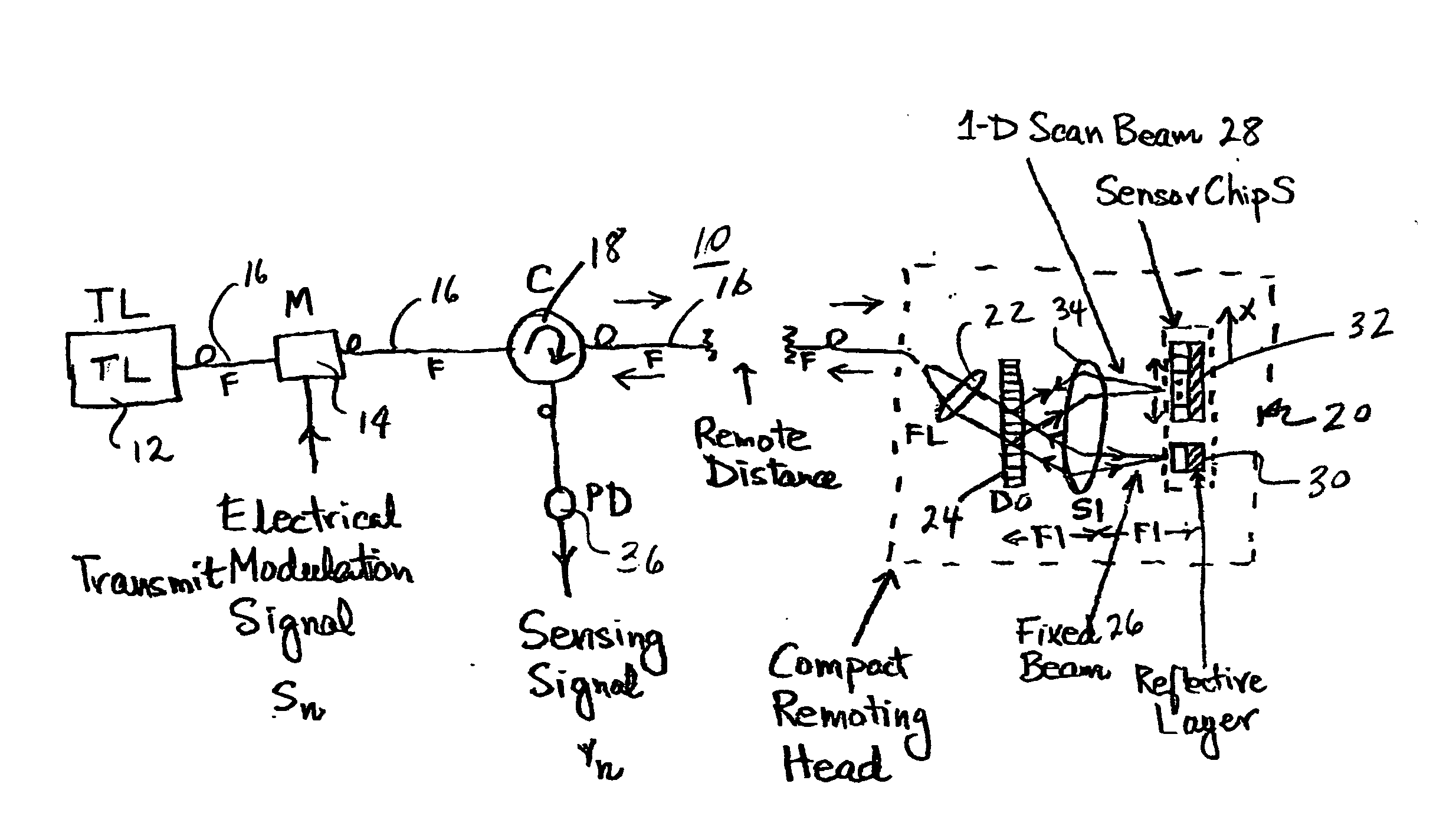
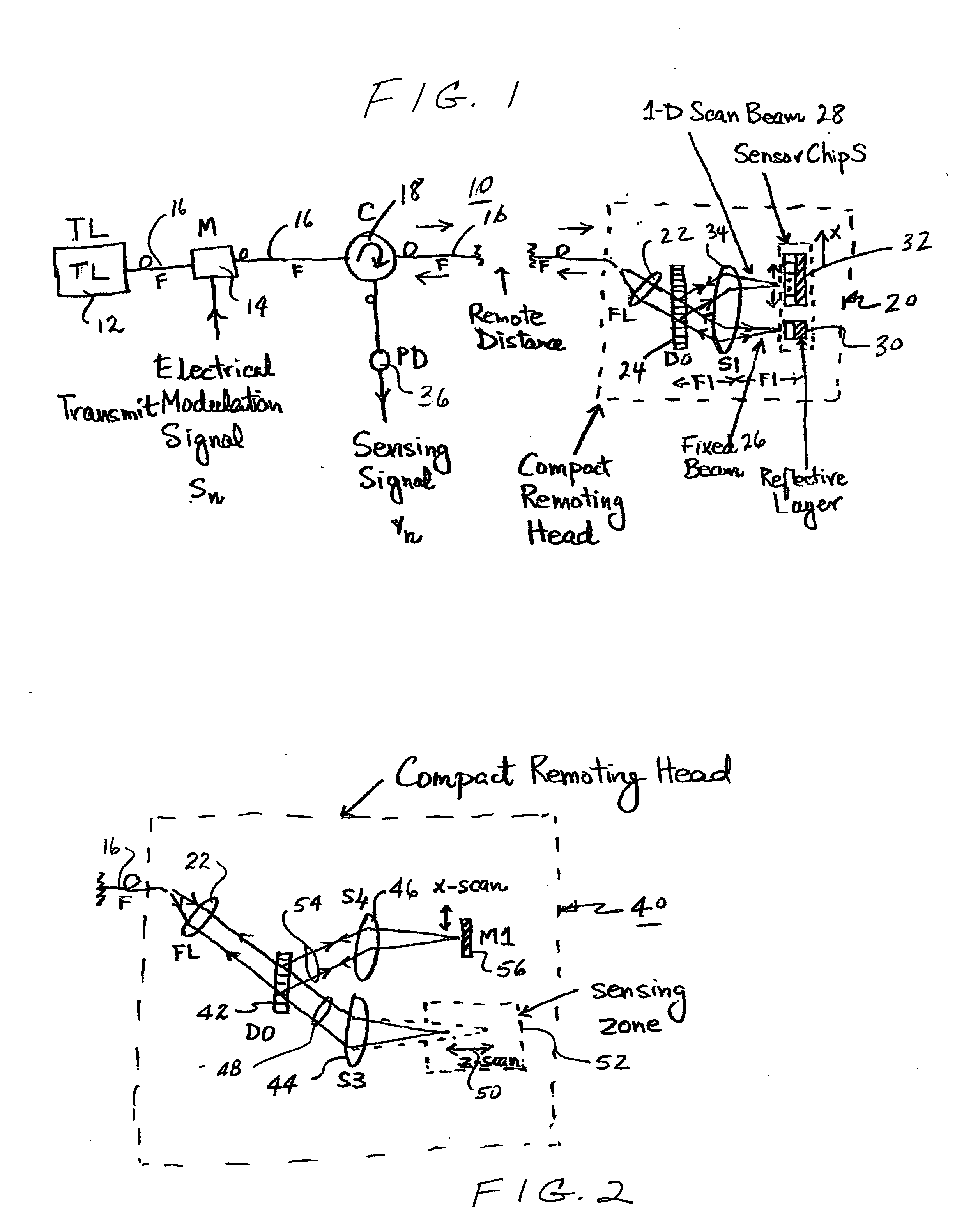
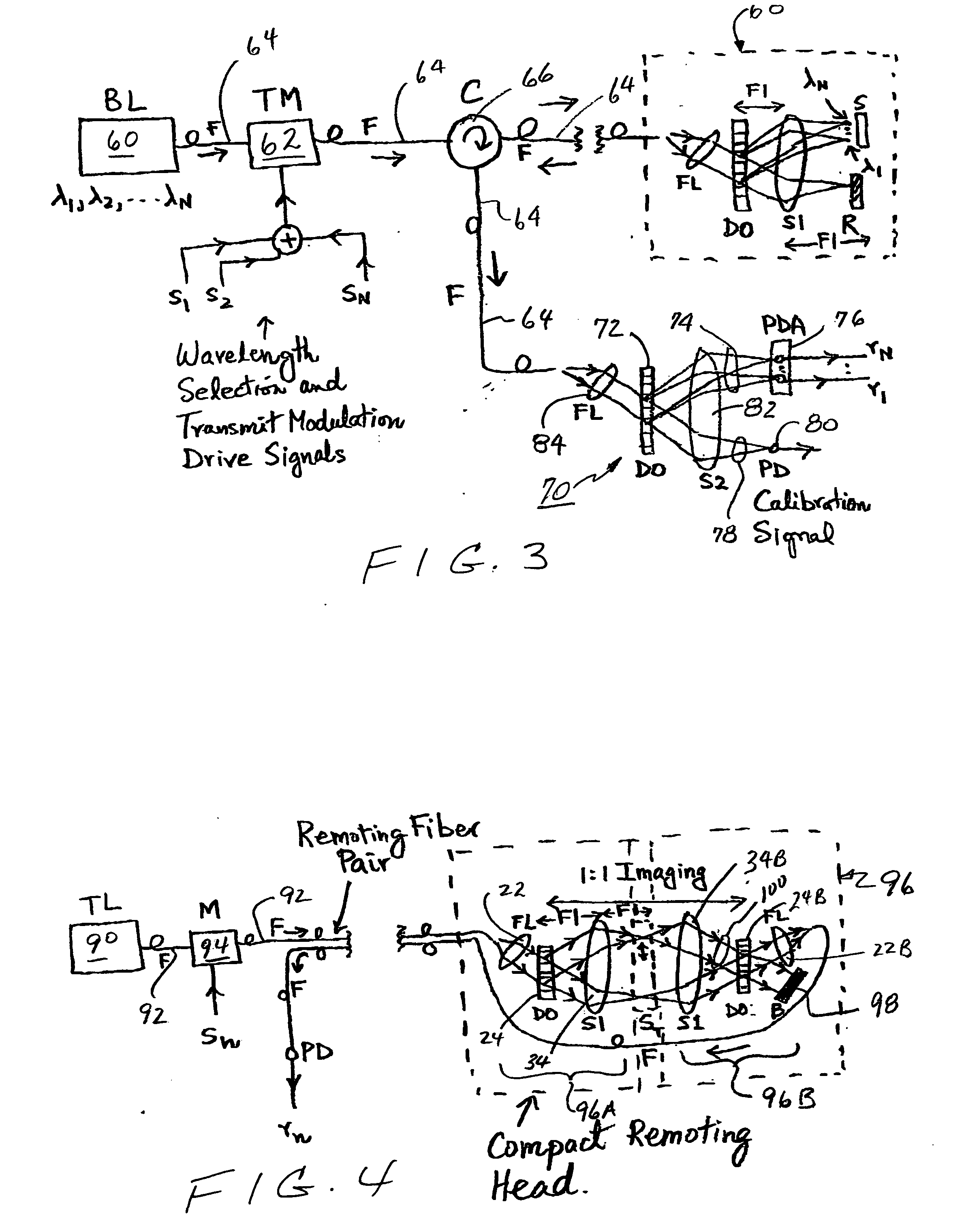
[0011] It is well known that changes of wavelength coupled with a wavelength dispersive optic can lead to one-dimensional (“1-D”) beam scans in freespace. This idea dates back to the 1970s, and has been explored to make optical scanners, optical radar, optical microscopy, optical printing, and optical memory system for holographic data recording. More recently, this wavelength tuning along with wavelength selection has been proposed for wide coverage optical laser scanners and optical data reading devices. In addition, wavelength tuning combined with traditional fiber-optics such as 2×2 couplers have been used to form interferometers. All these works are described in the following references: R. L. Forward, U.S. Pat. No. 3,612,659, Oct. 12, 1971; R. S. Hughes, et.al., U.S. Pat. No. 4,184,767, Jan. 22, 1980; K. G. Leib, U.S. Pat. No. 4,250,465, Feb. 10, 1981; K. G. Leib, U.S. Pat. No. 4,735,486, Apr. 5, 1988; T. Inagaki, U.S. Pat. No. 4,938,550, Jul. 3, 1990; B. Picard, U.S. Pat. No....


PUM


Abstract

An agile optical sensor based on scanning optical interferometry is proposed. The preferred embodiment uses a retroreflective sensing design while another embodiment uses a transmissive sensing design. The basic invention uses wavelength tuning to enable an optical scanning beam and a wavelength dispersive element like a grating to act as a beam splitter and beam combiner to create the two beams required for interferometry. A compact and environmentally robust version of the sensor is an all-fiber in-line low noise delivery design using a fiber circulator, optical fiber, and fiber lens connected to a Grating-optic and reflective sensor chip.

Description

SPECIFIC DATA RELATED TO THE INVENTION [0001] This application claims the benefit of U.S. Provisional Application No. 60 / 498,558 filed on Aug. 28, 2003.BACKGROUND OF THE INVENTION [0002] Scanning optical interferometry is the field of invention. It is well known that optical interferometry can be used to detect very small changes in optical properties of a material (e.g., refractive index, material thickness). These changes can be man-made such as on a phase-encoded optical security card or environmentally induced such as by temperature changes in a jet engine. [0003] Earlier, for example, acousto-optic devices or Bragg cells have been used to form scanning interferometers such as in N. A. Riza, “Scanning heterodyne acousto-optical interferometers,” U.S. Pat. No. 5,694,216, Dec. 2, 1997; N. A. Riza, “In-Line Acousto-Optic Architectures for Holographic Interferometry and Sensing,”OSA Topical Meeting on Holography Digest, pp. 13-16, Boston, May, 1996; N. A. Riza, “Scanning heterodyne ...

Claims


Application Information

Patent Timeline
Patent Type & Authority Applications(United States)
IPC IPC(8): G01B9/02G01D5/353
CPCG01D5/35303G01B9/02004G01B2290/45G01B9/02081G01B2290/30G01B9/02024
Inventor RIZA, NABEEL AGHAPEREZ, FRANK
Owner NUONICS
Why Eureka
Try Eureka