Conductive adhesive and piezo-electric device having piezo-electric element mounted thereon using such adhesive

a piezo-electric element and adhesive technology, applied in the direction of non-macromolecular adhesive additives, generators/motors, conductors, etc., can solve the problems of increased stress on the saw element, adverse effects on the characteristics of the saw element, and unsatisfactory stresses, etc., to achieve high frequency and high precision

Inactive Publication Date: 2005-04-21
SEIKO EPSON CORP
View PDF2 Cites 23 Cited by
  • Summary
  • Abstract
  • Description
  • Claims
  • Application Information

AI Technical Summary

Benefits of technology

[0008] The conductive adhesive of the present invention is capable of fully absorbing stress such as thermal deformation from seam welding the SAW device and realizing wire bonding having the proper state of joint. The conductive adhesive of the present invention permits a piezo-electric device of high quality and high reliability to be fabricated which, in addition to attaining high frequency and high precision, will be able to realize desirable vibration and temperature characteristics, and enhance bondability, that is, ease of joining of the SAW element to the piezo-electric element.

Problems solved by technology

This is conveyed to the SAW element through the adhesive, and may possibly affect its characteristics adversely.
Also, this may cause the adhesive to contract when the adhesive is baked and hardened, which may cause additional stress to act on the SAW element.
These stresses are not desirable and will affect achieving high frequency and high precision.
It is believed that such an adhesive composition when coated on a mounting surface of a base and hardened, will cause the three fillers to be unevenly distributed.
More importantly, when a bonding wire tip is pressed to a bonding pad surface using a wedge tool, the conventional adhesive undergoes elastic deformation and causes the SAW element to sink down.
If sinkage of the SAW element is too much, the load on the bonding wire and ultrasonic vibration disappear, thereby making it impossible to form a joint having a proper state.

Method used


Image

  • Conductive adhesive and piezo-electric device having piezo-electric element mounted thereon using such adhesive
  • Conductive adhesive and piezo-electric device having piezo-electric element mounted thereon using such adhesive
  • Conductive adhesive and piezo-electric device having piezo-electric element mounted thereon using such adhesive

Examples


embodiment 1

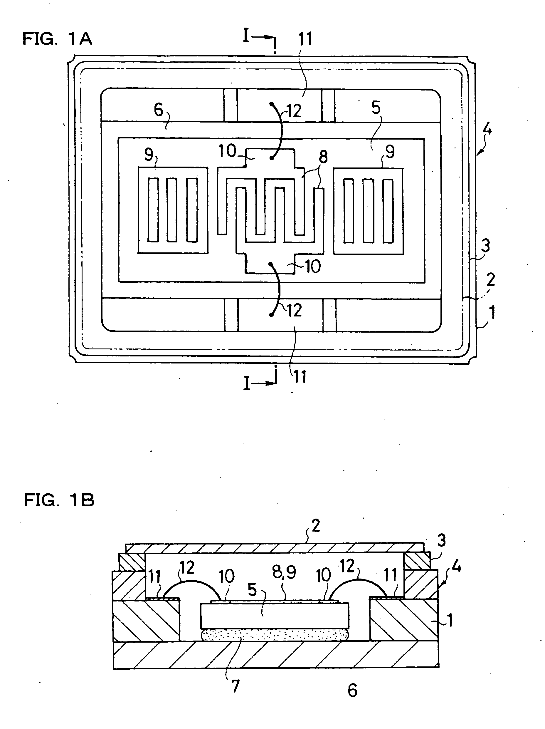
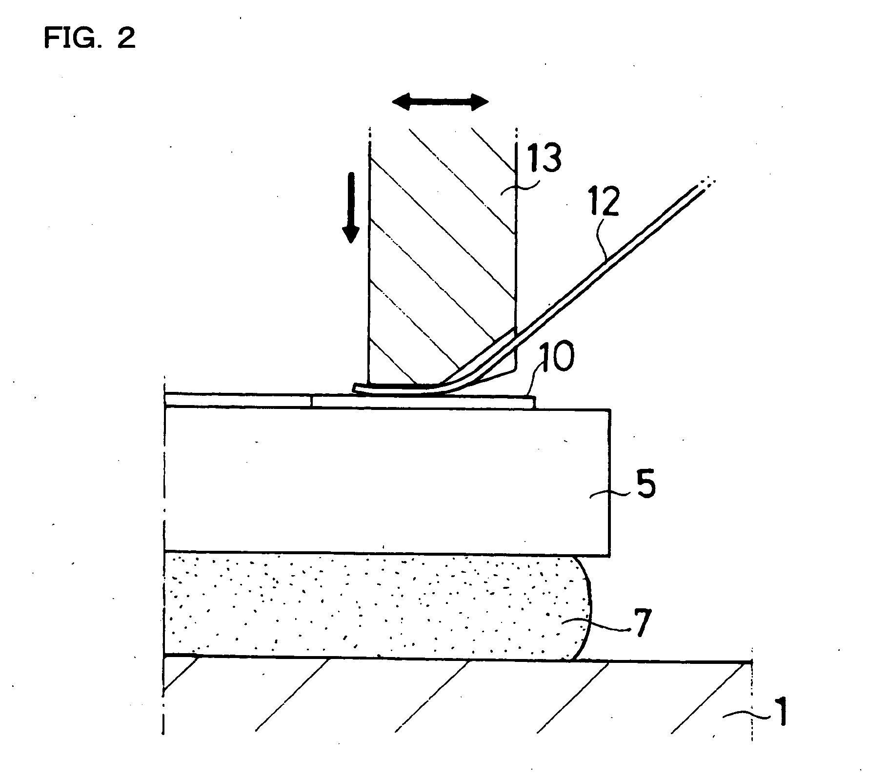
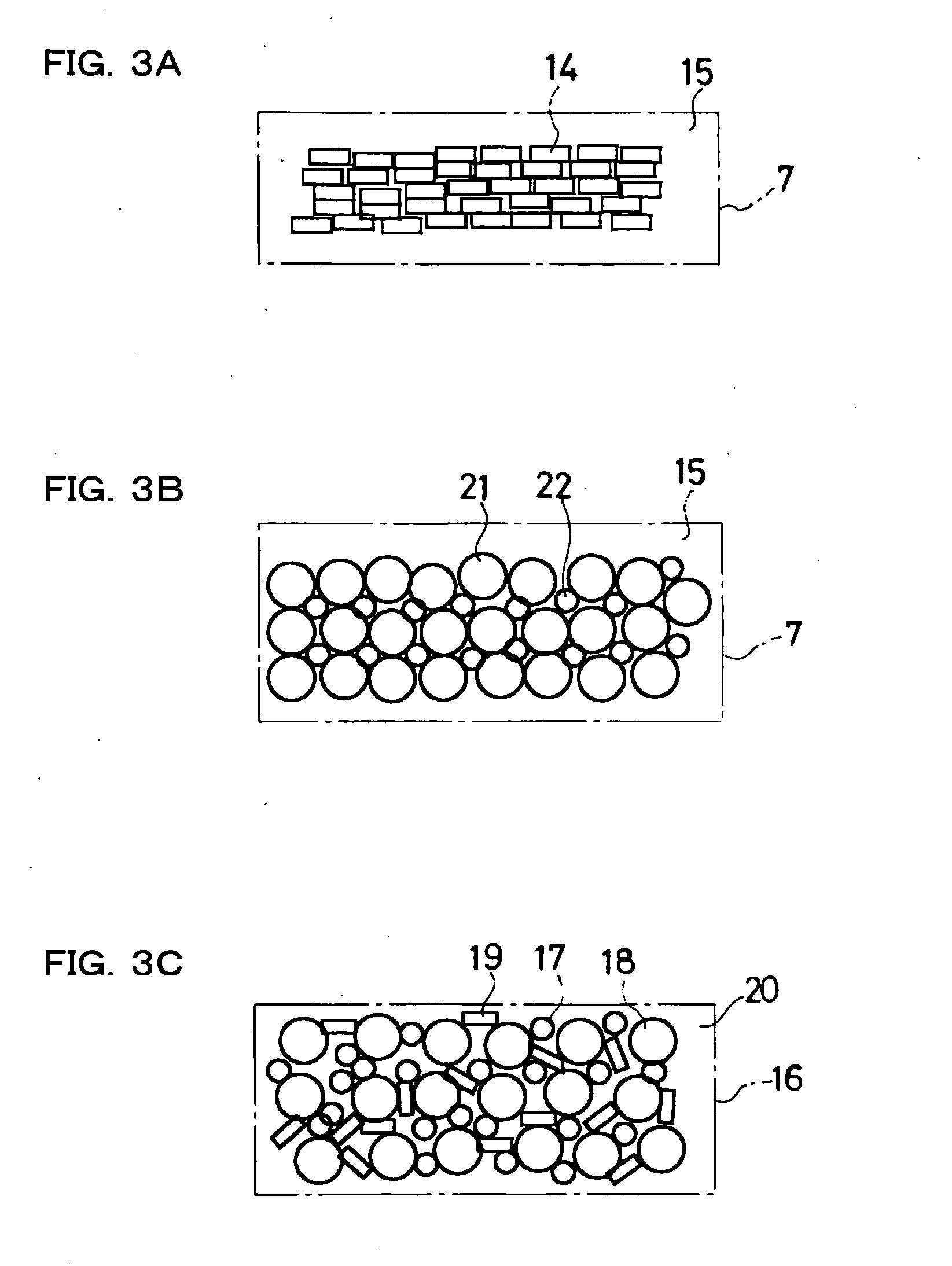
[0040] There were respectively manufactured an SAW resonator (this embodiment 1) to which an SAW element is bonded and affixed by using the conductive adhesive of a first embodiment of this invention mentioned above in connection with FIG. 3(A) and an SAW resonator (this embodiment 2) to which an SAW element is bonded and affixed by using the conductive adhesive of a second embodiment of this invention mentioned above in connection with FIG. 3(B). A die attachment condition or pressurizing force when bonding the SAW element to the mounting surface of the base was 20+ / −15 g / cm2 for both cases, and a hardening condition of the conductive adhesive was set to be N2 baking for 180° C.×1 hour for this embodiment 1 and vacuum baking for 280° C.×3 hours for this embodiment 2. For the bonding wire, an Al / Si 1% wire of a 40 μm diameter was used, and a commercially available full automatic ultrasonic wedge bonder was used to carry out wedge bonding at conditions of a processing time of 20 ms, ...


PUM

PropertyMeasurementUnit
particle diameteraaaaaaaaaa
lengthaaaaaaaaaa

Abstract

A piezo electric device in which a SAW element 5 is mounted on a base 1 of a package 4 having bonding pads 10,10 connected through bonding wires to corresponding connection terminals 11,11 in the package and having a lid 2 being joined to the base by seam welding and hermetically sealed thereto. The SAW element 5 is bonded and affixed to a mounting surface 6 in the base 1 using a conductive adhesive 7 which contains 80 to 85% resin material by weight and a 20 to 15% flaky conductive filler by weight, or using a conductive adhesive which contains 82.5 to 85% resin material by weight and a 17.5 to 15% conductive filler by weight, wherein the conductive filler comprises a 30% small particulate conductive filler 21 by weight and a 70% large particulate conductive filler 22 by weight.

Description

FIELD OF THE INVENTION [0001] This invention relates to a conductive adhesive composition and to a piezo-electric device, having, a package with for example, a piezo-electric element such as an SAW (surface acoustic wave) device mounted in the package and bonded to the piezo-electric element using the conductive adhesive composition. DESCRIPTION OF THE RELATED ART [0002] SAW devices such as resonators, filters, oscillators and the like utilizing an elastic surface wave SAW element excited by an IDT (interdigital transducer) consisting of interdigital electrodes formed on a surface of a piezo-electric substrate and a reflector are widely used for a variety of electronic apparatus and equipment. Particularly, in recent years, high frequency and high precision SAW devices capable of meeting high-speed requirements of communications are in demand in fields of communications equipment and the like. [0003] Typically, the SAW device utilizes a SAW element mounted in a package having a meta...

Claims


Application Information

Patent Timeline
Patent Type & Authority Applications(United States)
IPC IPC(8): C09J9/02C09J11/04C09J201/00H01B1/00H01B1/22H01L21/52H03H9/02H03H9/05H03H9/25
CPCH03H9/0585H03H9/1071H01L2224/4847H01L2224/85181H01L2224/48091H01L2224/73265H01L2224/45124H01L2924/00014H01L2924/00H01L2924/16195H01L21/52
Inventor IGUCHI, SHUICHI
Owner SEIKO EPSON CORP
Why Eureka
Try Eureka