System and method for stabilizing of internal structures

a stabilizing system and internal structure technology, applied in the field of bony structure stabilizing systems, can solve the problems of reducing the height of the disc space, affecting the placement of the percutaneously placed bone, and affecting the stability of the internal structure, so as to reduce the difficulty of percutaneous placemen

Active Publication Date: 2005-04-21
THEKEN SPINE
View PDF34 Cites 518 Cited by
  • Summary
  • Abstract
  • Description
  • Claims
  • Application Information

AI Technical Summary

Benefits of technology

[0011] In one embodiment, there is shown a system and method for reducing the difficulty in percutaneous placement of a spine stabilization brace by coupling the brace to a pedicle screw in a single assembly. The brace-screw assembly is delivered along with an anchor extension through a cannula for anchoring in the vertebrae pedicle. The anchor extension, which becomes a cannula for working on the brace from the exterior of the patient, is constructed with partial slot openings along two sides. Once the screw portion of the brace-screw assembly is locked in place with respect to the first vertebrae, the prox

Problems solved by technology

Over time, or because of accidents, the intervertebral discs loose height, become cracked, dehydrated, or are simply jarred out of position.
The result being that the disc space height is reduced leading to compression of the nerve bundles causing pain and in some cases damage to the nerves.
One problem when connecting the braces to the anchors is to position the braces in place as quickly as possible and without doing more damage to the surrounding tissue and muscle of the patient as is absolutely necessary.
It is diff

Method used


Image

  • System and method for stabilizing of internal structures
  • System and method for stabilizing of internal structures
  • System and method for stabilizing of internal structures

Examples


Embodiment Construction

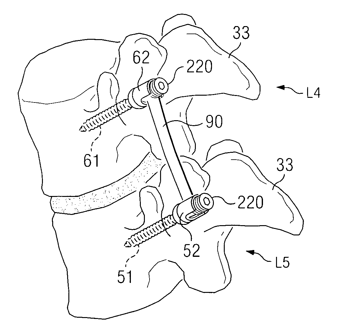
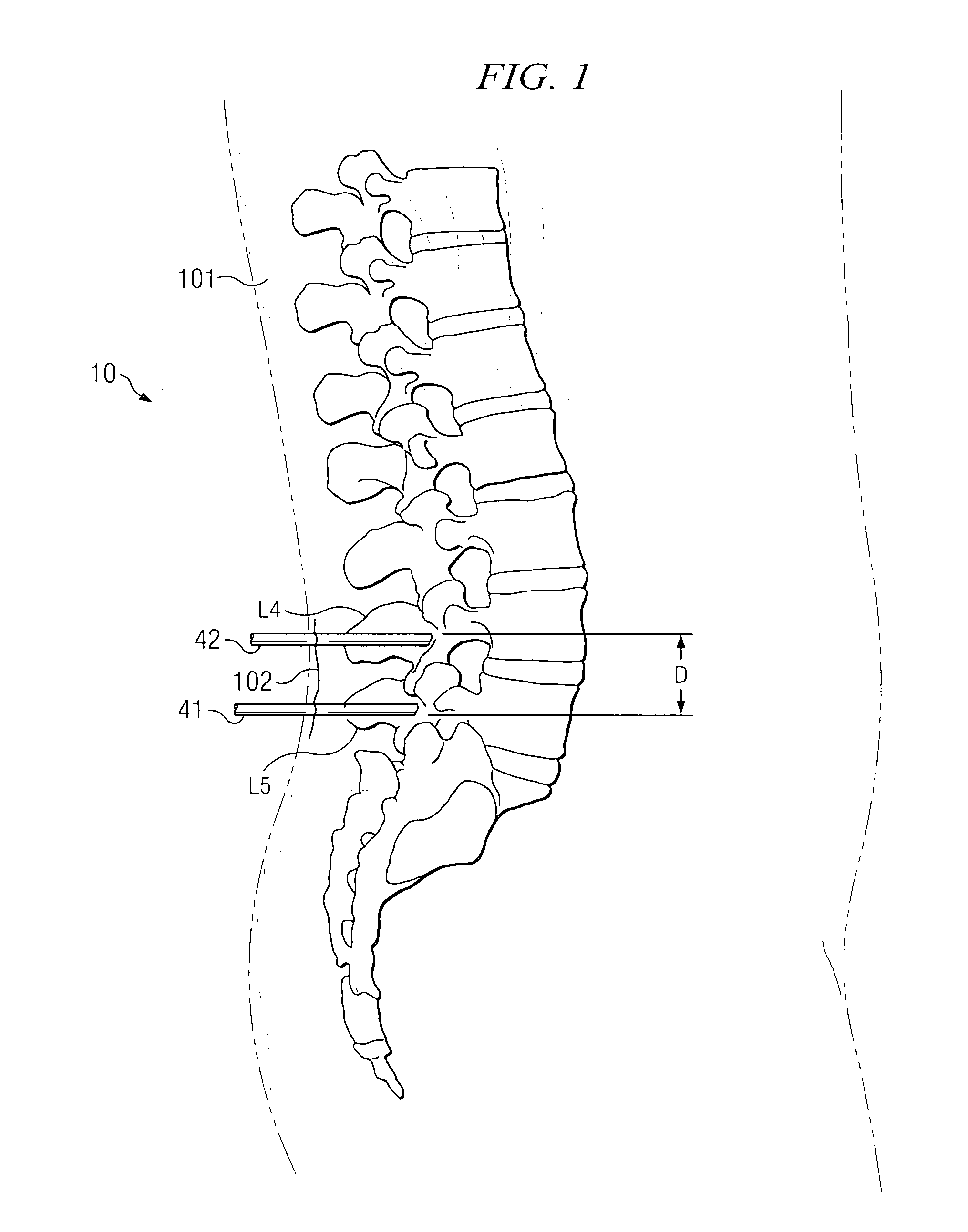
[0034] Turning now to FIG. 1, there is shown a sketch of human spine 10 showing a pair of tubes, or cannulas 41 and 42 extending through skin 101 into vertebrae L5 and L4. Cannula 41 is positioned over the pedicle of vertebrae L5 (as will be discussed), and cannula 42 is positioned over the pedicle of vertebrae L4. This procedure is being illustrated with respect to vertebrae L4 and L5 but could be performed with respect to any vertebrae or with respect to any bony portions of the body (human or animal) where a brace is to be placed between two points. The distance D is variable as desired. The sketch of FIG. 1, as are the sketches shown in other figures, are not to scale and are shown for illustration purposes with angles selected for clarity of explanation and not necessarily selected to be anatomically correct.

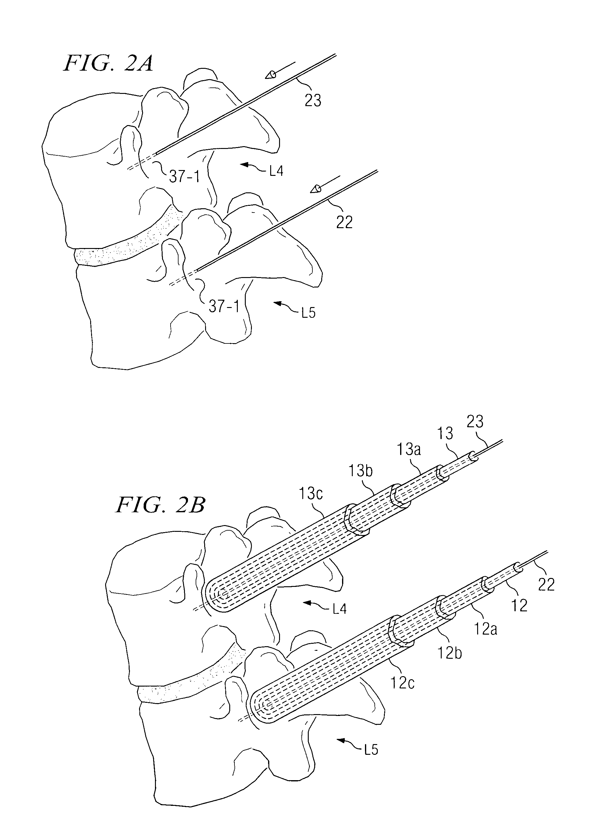
[0035] The procedure to insert the brace between vertebrae L5 and L4 is as follows: The surgeon identifies the desired vertebral levels and pedicle positions via standard ...


PUM


Abstract

There is shown a system and method for reducing the difficulty in percutaneous placement of a spine stabilization brace by coupling the brace to a pedicle screw in a single assembly. The brace-screw assembly is delivered along with an anchor extension through a cannula for anchoring in the vertebrae pedicle. The anchor extension becomes a cannula for working on the brace from the exterior of the patient, as constructed with a slot opening along two sides. Once the screw portion of the brace-screw assembly is locked in place with respect to the first vertebra, the proximal end of the brace is below the skin line. The brace is then repositioned so that the proximal end leaves the cannula through one slot and is captured by a corresponding slot positioned in a second cannula coupled to a second anchor. Once captured, the proximal end of the brace is guided by the second cannula to a receptacle positioned in the second vertebra.

Description

TECHNICAL FIELD [0001] This invention relates to bony structure stabilization systems and more particularly to systems and methods for percutaneously inserting a pedicle screw stabilization device. BACKGROUND OF THE INVENTION [0002] The human spine provides a vast array of functions, many of which are mechanical in nature. The spine is constructed to allow nerves from the brain to pass to various portions of the middle and lower body. These nerves, typically called the spinal cord, are located in a region within the spine called the neuro canal. Various nerve bundles emerge from the spine at different locations along the lateral length of the spine. In a healthy spine, these nerves are protected from damage and / or undue pressure thereon, by the structure of the spine itself. [0003] The spine has a complex curvature made up of a plurality (24 in all) of individual vertebrae separated by intervertebral discs. These discs hold the vertebrae together in a flexible manner so as to allow ...

Claims


Application Information

Patent Timeline
IPC IPC(8): A61B17/70A61B17/88
CPCA61B17/1757A61B17/1655A61B17/7002A61B17/7005A61B17/701A61B17/7011A61B17/7032A61B17/7037A61B17/7038A61B17/7082A61B17/7085A61B2017/320044A61B2019/461A61B2019/467A61B17/3468Y10S606/914A61B2090/067A61B2090/061
Inventor SPITLER, JAMESSCHORER, SCOTT
Owner THEKEN SPINE
Why Eureka
Try Eureka