Adjustment of amplitude and DC offsets in a digital receiver

a digital receiver and amplitude technology, applied in the field of data communication, can solve the problems of signal spectrum, performance degradation, and inability to suppress dc which is 100 db above the level of the received signal, and achieves the effect of low gate count, fast adaption to changing dc levels, and low cos

Inactive Publication Date: 2005-04-28
TEXAS INSTR INC
View PDF7 Cites 19 Cited by
  • Summary
  • Abstract
  • Description
  • Claims
  • Application Information

AI Technical Summary

Benefits of technology

[0014] An advantage of the present invention is that the DC compensation mechanism can be implemented in a relatively small size (i.e. low gate count) and adapts quickly to changing DC levels. This is in comparison to prior art solutions based on linear filtering that require relatively high gate counts to achieve sufficient filtering and have extended adaptation times. Another advantage is that in applications where the input signal is at low IF (i.e. near zero IF), the nonlinear nature of the mechanism of the present invention permits adaptation to any DC level without distorting the signal itself even in the case of near zero IF. This is in contrast to prior art solutions where filtering distorts the signal's spectrum and causes performance degradation. For example, suppressing DC which is 100 dB above the level of the received signal and is very close to it in frequency (IF of 500 kHz) is almost impossible using linear filtering.
[0015] Another advantage is that the DC compensation mechanism of the present invention provides fine DC offset cancellation using the multi-stage architecture wherein the final stage operates on a scaled signal. A further advantage is the very low gate count to implement the mechanism stemming from the reuse of the DC estimation hardware.
[0016] Note that many aspects of the invention described herein may be constructed as software objects that are executed in embedded devices as firmware, software objects that are executed as part of a software application on either an embedded or non-embedded computer system running a real-time operating system such as WinCE, Symbian, OSE, Embedded LINUX, etc. or non-real time operating system such as Windows, UNIX, LINUX, etc., or as soft core realized HDL circuits embodied in an Application Specific Integrated Circuit (ASIC) or Field Programmable Gate Array (FPGA), or as functionally equivalent discrete hardware components.
[0017] There is thus provided in accordance with the present invention a method of DC offset estimation, the method comprising the steps of determining a current maximum peak value of an input signal, determining a current minimum peak value of the input signal and calculating an average of the current maximum peak value and the current minimum peak value to yield a DC offset estimate.
[0018] There is also provided in accordance with the present invention an apparatus for DC offset compensation comprising first means for determining a current maximum peak value of an input signal comprising, means for comparing the input signal with a previous maximum peak value, means for adding the current maximum peak value to a first difference between the input signal and the previous maximum peak value, the first difference multiplied by a maximum charge coefficient to yield the current maximum peak value if the input signal is greater than the previous maximum peak value, means for subtracting a second difference between the current maximum peak value and the input signal multiplied by a maximum discharge coefficient from the previous maximum peak value to yield the current maximum peak value if the input signal is not greater than the previous maximum peak value, second means for determining a current minimum peak value of the input signal comprising, means for comparing the input signal with a previous minimum peak value, means for subtracting a first difference between the current minimum peak value and the input signal, the first difference multiplied by a minimum discharge coefficient and subtracted from the previous minimum peak value to yield the current minimum peak value if the input signal is greater than the previous maximum peak value, means for adding the current minimum peak value to a second difference between the input signal and the previous minimum peak value, the second difference multiplied by a minimum charge coefficient to yield the current minimum peak value if the input signal is not greater than the previous minimum peak value, third means for calculating an average of the current maximum peak value and the current minimum peak value to yield a DC offset estimate and fourth means for subtracting the DC offset estimate from the input signal to yield a DC offset compensated output signal.
[0019] There is further provided in accordance with the present invention an method of amplitude adjustment and DC offset compensation, the method comprising the steps of first performing coarse DC offset compensation comprising the steps of determining a first current maximum peak value of an input signal, determining a first current minimum peak value of the input signal, calculating an average of the first current maximum peak value and the first current minimum peak value to yield a first DC offset estimate, subtracting the first DC offset estimate from the input signal to yield a first DC offset compensated signal, scaling the first DC offset compensated signal to within a predefined range of amplitudes to yield a scaled signal, second performing fine DC offset compensation comprising the steps of determining a second current maximum peak value of the scaled signal, determining a second current minimum peak value of the scaled signal, calculating an average of the second current maximum peak value and the second current minimum peak value to yield a second DC offset estimate and subtracting the second DC offset estimate from the scaled signal to yield an output DC offset compensated signal.

Problems solved by technology

This is in contrast to prior art solutions where filtering distorts the signal's spectrum and causes performance degradation.
For example, suppressing DC which is 100 dB above the level of the received signal and is very close to it in frequency (IF of 500 kHz) is almost impossible using linear filtering.

Method used


Image

  • Adjustment of amplitude and DC offsets in a digital receiver
  • Adjustment of amplitude and DC offsets in a digital receiver
  • Adjustment of amplitude and DC offsets in a digital receiver

Examples


Embodiment Construction

Notation Used Throughout

[0032] The following notation is used throughout this document.

TermDefinitionAFCAutomatic Frequency ControlAGCAutomatic Gain ControlAHDLAdaptive Hard Decision LogicAPSAdaptive PrescalerASICApplication Specific Integrated CircuitBERBit Error RateDCDirect CurrentDCOCDC Offset CompensationFPGAField Programmable Gate ArrayGFSKGaussian Frequency Shift KeyingHDLHardware Description LanguageIFIntermediate FrequencyPSPrescalerRFRadio FrequencyRSSIReceive Signal Strength Indicator

DETAILED DESCRIPTION OF THE INVENTION

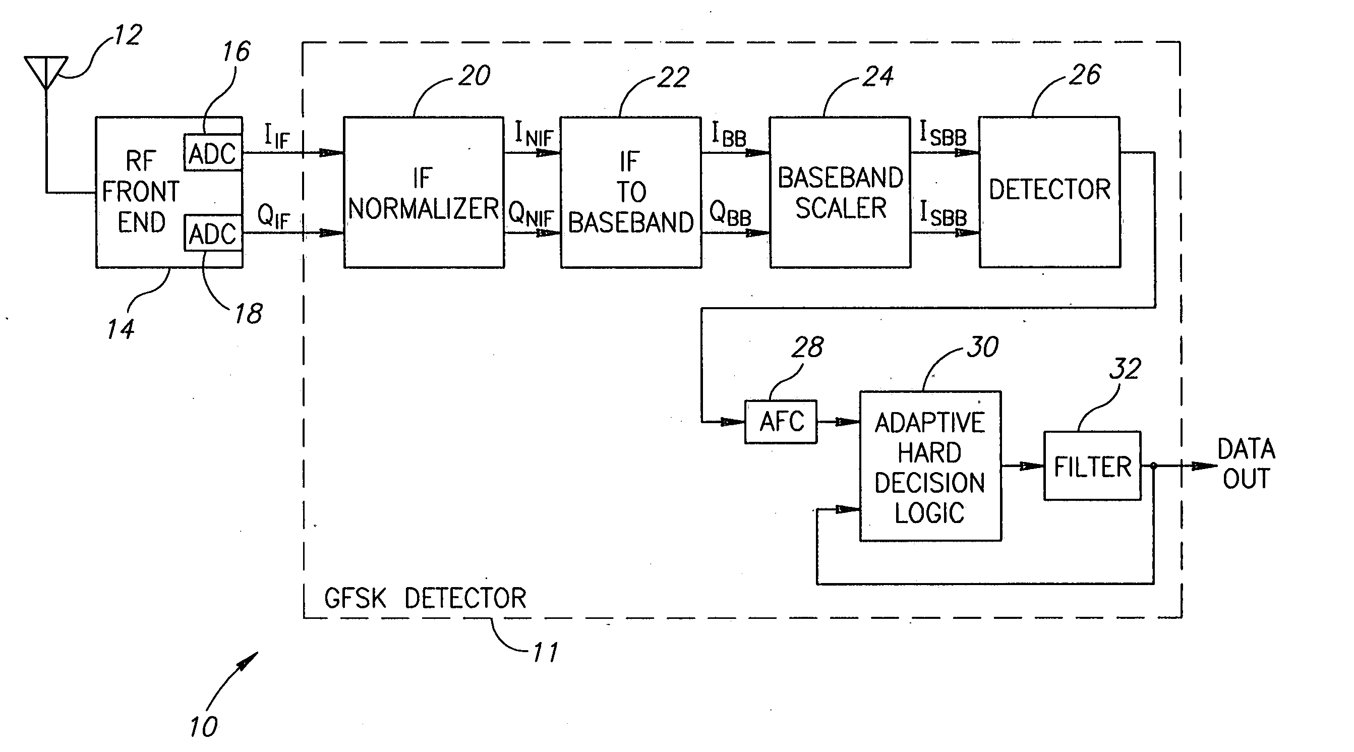
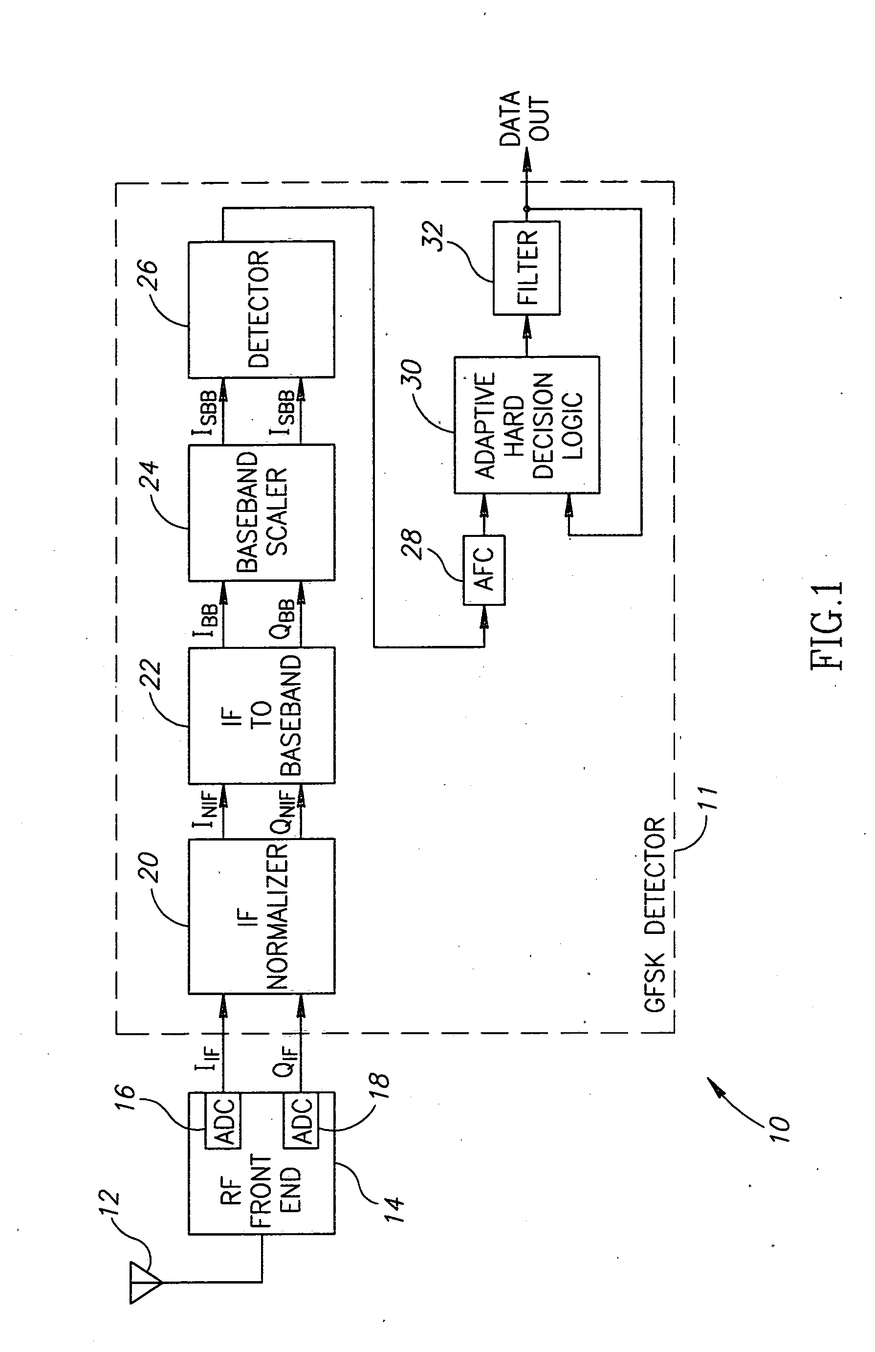
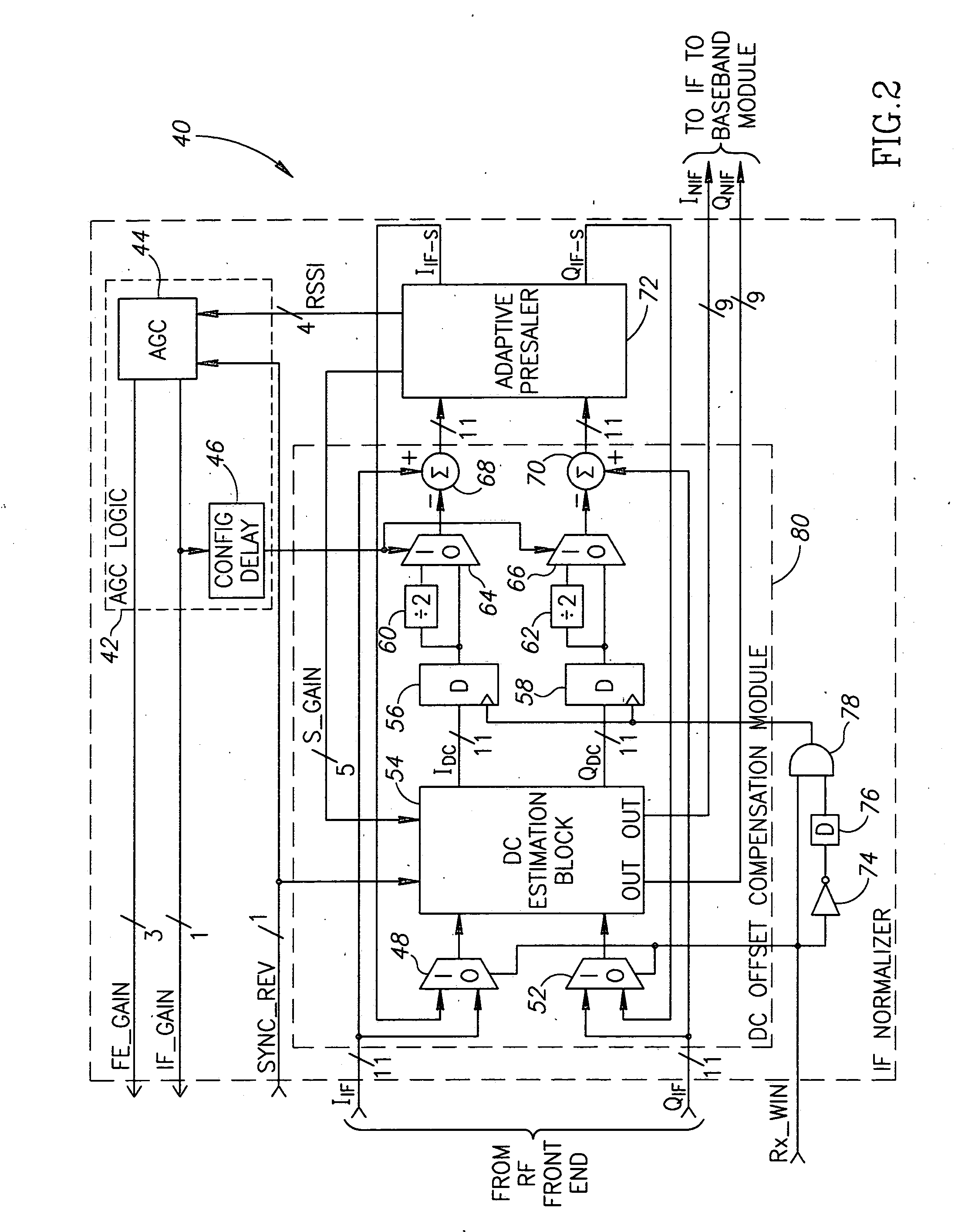
[0033] The present invention is a mechanism for amplitude adjustment and DC offset compensation. The mechanism functions to normalize the signal output from the RF front portion of a receiver before it is converted from IF to Zero-IF. The present invention is well suited for use in a digital receiver such as a Gaussian Frequency Shift Keying (GFSK) detector constructed according to the Bluetooth specification.

[0034] It is noted that the present invent...


PUM


Abstract

A nonlinear adaptive mechanism for amplitude adjustment and DC estimation and compensation for use in a digital receiver such as a Bluetooth GFSK receiver. The mechanism uses a feed-forward technique that can be used in a multi-stage scheme to perform both DC compensation and amplitude adjustment of an input signal for use by subsequent processing stages. In a first stage, coarse DC offset compensation is performed and the offset estimates generated are subsequently frozen. In a second stage, the incoming signal with the DC offset subtracted from it, is then scaled into a narrow predefined range of amplitudes using a scaling mechanism that works with gains and attenuations that are powers of two in order to simplify implementation. In a third stage, the scaled compensated signal is then injected again into the same DC estimation mechanism, which was previously used for DC compensation in the first stage, for further DC offset estimation and compensation (i.e. fine DC estimation and compensation).

Description

FIELD OF THE INVENTION [0001] The present invention relates to the field of data communications and more particularly relates to a method of and apparatus for adjustment of amplitude and DC offsets in a digital receiver. BACKGROUND OF THE INVENTION [0002] In digital communications systems, a carrier signal is modulated with the digital data to be transmitted over the channel, where it typically suffers various forms of distortion, such as additive noise. The digital data is often transmitted in bursts wherein each burst consists of a number of data bits. Upon reception, the signal must be demodulated in order to recover the transmitted data. [0003] It is common for receivers to employ direct conversion (i.e. homodyne receiver) to perform the demodulation of the received signal. The received signal is mixed with a~local oscillator signal at the carrier frequency to produce I (in-phase) and Q (quadrature) baseband signals. An advantage of direct conversion receivers is that they are e...

Claims


Application Information

Patent Timeline
Patent Type & Authority Applications(United States)
IPC IPC(8): H04L25/06
CPCH04L25/061
Inventor SUISSA, UDIELIEZER, ORENKATZ, RAN
Owner TEXAS INSTR INC
Why Eureka
Try Eureka