Reconfigurable parasitic control for antenna arrays and subarrays

a parasitic control and antenna array technology, applied in the field of antennas, can solve the problems of limited performance of phased array antennas, and control of the characteristics of antenna arrays, so as to reduce the number of problems, increase the scan angle, and reduce the effect of interferen

Inactive Publication Date: 2005-04-28
TOYON RES CORP
View PDF35 Cites 116 Cited by
  • Summary
  • Abstract
  • Description
  • Claims
  • Application Information

AI Technical Summary

Benefits of technology

[0014] Specifically, this invention builds on parent application Ser. No. 10 / 206,101 that describes the use of loaded parasitic components within the radiating aperture of an antenna element for the purpose of controlling the RF properties of the antenna element. It also describes the use of a feedback control subsystem that is part of the antenna system which adjusts the RF properties of the parasitic components based on some observed metric of the received waveform. This antenna system is referred to as a controlled parasitic antenna (CPA). By using a feedback control subsystem to control the electromagnetic properties of the antenna aperture, this antenna system can provide multifunctionality and / or mitigate problems associated with reception of an interfering signal or signals within a very compact volume.
[0015] In the present invention, by controlling reactive loads or switches attached to a parasitic element collocated with the individual radiating elements within an array or a subarray we can control the frequency properties of the array can be controlled and the scan angles can be increased. This approach holds promise for overcoming many of the limitations of current phased arrays.
[0016] One way of increasing the coverage of the array is by the use of reconfigurable elements. Such elements make use of one or more active control devices embedded in the aperture (specifically in parasitic elements in the aperture) of the individual radiating elements within the array. The impedance of the control device or devices would depend on the value of an applied bias voltage V or voltages (V1, V2, . . . ). A change in bias values would change the impedances and, consequently, the antenna properties of the element would change. This means that the embedded element gain and the active reflection coefficient become functions of V or (V1, V2, . . . ) as well as θ. That is, these factors in Expression (1) above can be expressed as g(θ, V1, V2, . . . ) and Γ(θ, V1, V2, . . . ). This disclosure teaches that it is possible to design reconfigurable elements so that the coverage of the array can be expanded considerably by varying the state of the elements.
[0017] It will also be shown that the implementation of two-state (switchable) devices as controls could be very effective for expanding the coverage of a phased array system. The bias voltages would only need to take on two different values (usually 0 volts and some other voltage that exceeds a switching threshold). The number of independent biases needed would depend on the number of two-state devices per element.

Problems solved by technology

The antenna array characteristics are also controlled, and usually limited, by the properties of the individual elements in the antenna array and the way in which they interact with each other.
For all of their advantages, however, performance of phased array antennas is limited.
Phased arrays are usually limited in the range of angles over which they can effectively steer a beam without significant losses in overall system gain.
This leads to an increase in |Γ(θ)| and, consequently, the system may not be able to meet specifications for that range of angles.
In addition, for high gain arrays, beam squint is usually the limiting factor on instantaneous bandwidth.

Method used


Image

  • Reconfigurable parasitic control for antenna arrays and subarrays
  • Reconfigurable parasitic control for antenna arrays and subarrays
  • Reconfigurable parasitic control for antenna arrays and subarrays

Examples


Embodiment Construction

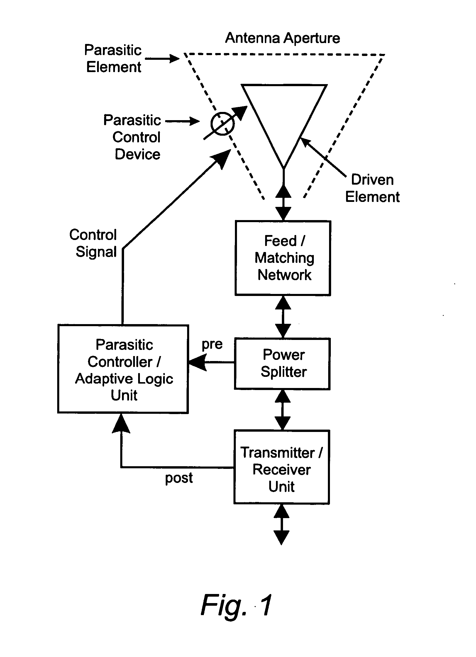
[0045]FIG. 1 shows a schematic representation of a single-element controlled parasitic antenna (CPA). The CPA (as taught in parent application Ser. No. 10 / 206,101) makes use of a feedback loop to adaptively determine the value of the control signal that will control the parasitic control device placed in or to the parasitic control element in the aperture of the antenna. This feedback loop contains a controller which has an adaptive logic unit, a control signal circuit, and the control device. The control device can be either a two state switch, which usually manifests itself as a two-state reactance, or it can be a continuously variable device (or multiple devices) such as a variable capacitor or varactor used by itself or as part of a control circuit. The feedback loop can tap the output either before (pre) or after (post) the receiver.

[0046] There may be situations where both pre and post feedback loops are used. Examples might be where a return loss (VSWR) signal is measured af...


PUM


Abstract

Reconfiguration of parasitically controlled elements in a phased array is used to expand the range of operational functions. Embedded array elements can be frequency tuned, and bandwidth can be improved by using reconfiguration to broaden the bandwidth of the embedded elements. For high gain arrays, beam squint can be a limiting factor on instantaneous bandwidth. Reconfiguration can alleviate this problem by providing control of the element phase centers. Scan coverage can be improved and scan blindness alleviated by controlling the embedded antenna patterns of the elements as well as by providing control of the active impedance as the beam is scanned. Applying limited phase control to the elements themselves can alleviate some of the complexity of the feed manifold. A presently preferred method of designing reconfigurable antennas is to selectively place controlled parasitic elements in the aperture of each of the antenna elements in the phased array. The parasitic elements can be controlled to change the operational characteristics of the antenna element. The parasitic elements are controlled by either switching load values in and out that are connected to the parasitic elements or are controlled by applying control voltages to variable reactance circuits containing devices such as varactors. The parasitic elements can be controlled by the use of a feedback control subsystem that is part of the antenna system which adjusts the RF properties of the parasitic components based on some observed metric. The controllable characteristics include directivity control, tuning, instantaneous bandwidth, and RCS.

Description

RELATED APPLICATIONS [0001] This is a continuation-in-part of commonly assigned application Ser. No. 10 / 206,101 filed Jul. 29, 2002 entitled “a Small Controlled Parasitic Antenna System and Method for Controlling Same to Optimally Improve Signal Quality” and naming Thomas L. Larry as sole inventor.BACKGROUND OF THE INVENTION [0002] 1. Field of the Invention [0003] The present invention relates to the field of antennas. Specifically, it relates to the control (including beam and null steering and tuning) of phased arrays and subarrays by using parasitic control elements in the aperture of each individual antenna element in the array. [0004] 2. Related Art [0005] Array antennas refer to the class of antennas which are formed by phase-coherent combining of the outputs from multiple stationary antenna elements. The array antenna's spatial beam pointing characteristics are determined by the positions of the individual radiators (elements) and the amplitudes, phases, and time-delays of th...

Claims


Application Information

Patent Timeline
Patent Type & Authority Applications(United States)
IPC IPC(8): H01Q1/36H01Q3/26H01Q11/08
CPCH01Q1/36H01Q11/08H01Q3/267
Inventor LARRY, THOMAS L.VANBLARICUM, MICHAEL L.RICHEN, ANDREW S.
Owner TOYON RES CORP
Why Eureka
Try Eureka