Differential amplifier

Active Publication Date: 2005-04-28
RENESAS ELECTRONICS CORP
View PDF8 Cites 7 Cited by
  • Summary
  • Abstract
  • Description
  • Claims
  • Application Information

AI Technical Summary

Benefits of technology

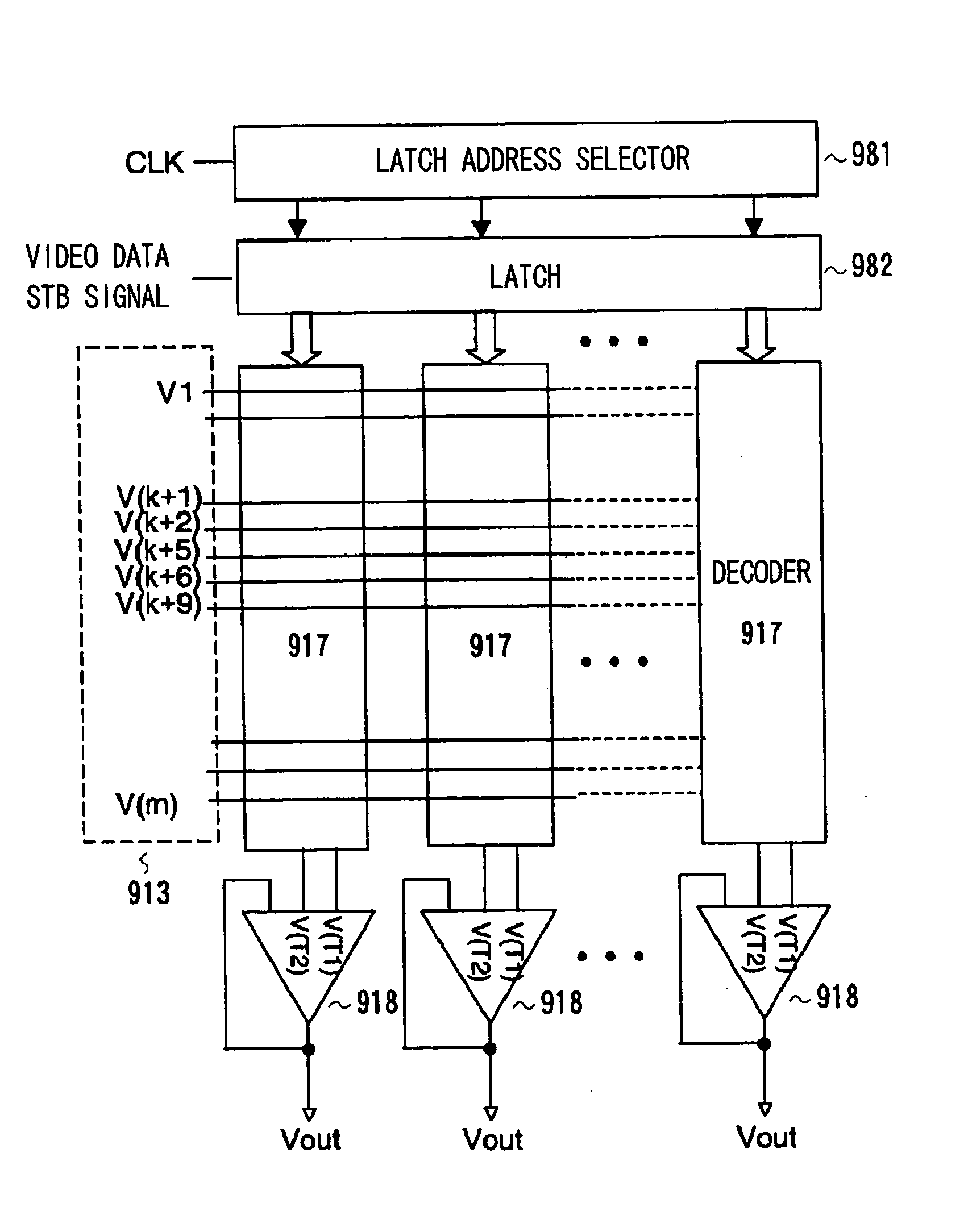
[0035] Accordingly, when the differential amplifier shown in FIG. 32 is employed in the output buffer circuit 988 of the data driver in the liquid crystal device shown in FIG. 31, a proportion capable of reducing the number of data lines is reduced. For this reason, there is a (third) problem that the effect of reducing the circuit size of the decoders 987 and reducing the area of the data driver LSI is reduced.
[0108] According to the present invention, by employing the differential amplifier and decoder described above, a data driver LSI that achieves area saving and low cost becomes possible. Alternatively, cost reduction and the narrower frame of a display device including the data driver also become possible.

Problems solved by technology

Accordingly, when the differential amplifier in FIG. 32 is used for the output buffer circuit of the data driver in the liquid crystal display device, there is a (second) problem that the differential amplifier can only be applied to the intermediate portion of the grayscale data.

Method used


Image

  • Differential amplifier
  • Differential amplifier
  • Differential amplifier

Examples


second embodiment

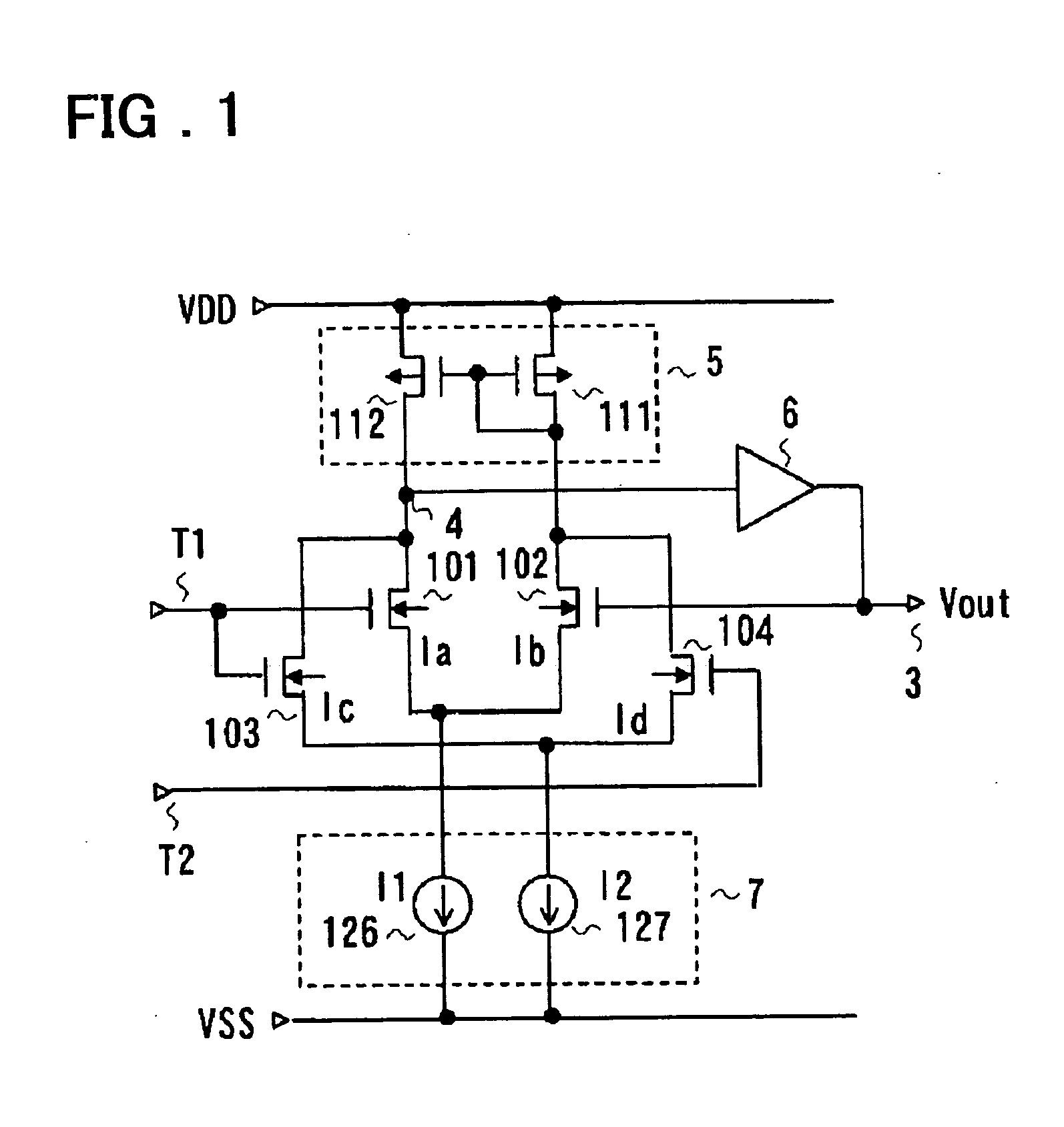
[0206]FIG. 7 is a diagram showing the present invention. Referring to FIG. 7, same reference numerals and characters are assigned to elements that are the same as or comparable to those in FIG. 1. Referring to FIG. 7, this embodiment further includes an input control circuit 8 in addition to the configuration in FIG. 1. Other configurations are same as the configuration in FIG. 1. More specifically, referring to FIG. 7, this embodiment includes the input control circuit 8 for performing control (selection) of input of two input voltages (Vi1, Vi2) to the input terminals T1 and T2 in the differential amplifier in FIG. 1. The input control circuit 8 is constituted from switches 151 and 152 connected between a terminal to which the voltage Vi1 is given and the terminals T1 and T2, respectively, and switches 154 and 155 connected between a terminal to which the voltage Vi2 is given and the terminals T1 and T2, respectively.

[0207] By controlling on and off of the switches 151, 152, 154, ...

third embodiment

[0208]FIG. 8 is a diagram showing a configuration of the present invention. In FIG. 8, the same reference numerals and characters are assigned to the elements that are the same or comparable to those in FIG. 1. Referring to FIG. 8, a specific example of a current control circuit 7 that performs current control over the currents I1 and I2 flown through the two differential pairs (101, 102) and (103, 104) is shown.

[0209] Referring to FIG. 8, the current control circuit 7 includes the current sources 126 and 127 constituted from transistors, and bias voltages VB11 and VB12 are fed to respective gates thereof. The bias voltages VB11 and VB12 may be fixed voltages, bias levels can be changed as necessary, and the current values of the currents I1 and I2 can also be changed.

fourth embodiment

[0210]FIG. 9 is a diagram showing a configuration of the present invention, and is the diagram showing an example of a modification of the current mirror circuit 5 in the differential amplifier in FIG. 1.

[0211] Referring to FIG. 9, the same reference numerals and characters are assigned to the elements that are the same or comparable to those in FIG. 1.


PUM


Abstract

A differential amplifier has first and second input terminals (T1, T2), an output terminal, a differential stage connected to the first and second input terminals, and an amplification stage having an input terminal thereof connected to an output terminal of the differential stage and an output terminal thereof connected to the output terminal. The differential stage includes a first differential pair with one of an input pair thereof connected to the first input terminal (T1) and the other connected to the output terminal, a second differential pair with one of an input pair thereof connected to the first input terminal (T1) and the other connected to the second input terminal (T2), a first current source for supplying current to the first differential pair, a second current source for supplying current to the second differential pair, and a load circuit connected to the output pairs of the first and second differential pairs. One of the output pair of the first differential pair is connected in common to one of the output pair of the second differential pair, and their common connection node constitutes the output terminal of the differential stage.

Description

FIELD OF THE INVENTION [0001] The present invention relates to a differential amplifier. More specifically, the invention relates to a differential amplifier suitable for being applied to a data driver in a liquid crystal display device and the like, and a display device that uses it. BACKGROUND OF THE INVENTION [0002] Recently, a liquid crystal display device (LCD), featured by thin thickness, lightness of weight and low power consumption, has become popular as a display device, and is now in use for a display device of a mobile information terminal device, such as a portable telephone set (mobile phone or cellular phone), PDA (personal digital assistant) or a notebook PC. [0003] However, the technique for enlarging the size of the liquid crystal display device or for coping with moving pictures has advanced such that not only the LCD for mobile use but also the stationary type large screen display device or a large screen liquid crystal television receiver has become a reality. As...

Claims


Application Information

Patent Timeline
IPC IPC(8): G02F1/133G09G3/36G09G3/20H03F1/34H03F3/34H03F3/45
CPCG09G3/3688G09G3/2011
Inventor TSUCHI, HIROSHI
Owner RENESAS ELECTRONICS CORP
Why Eureka
Try Eureka