Optimized mirror design for optical direct write

a mirror design and optical direct writing technology, applied in the field of direct writing patterns, can solve the problems of disproportionate costs to the costs involved, large difficulty in patterning features using conventional photolithography, and high cost of masks or reticles, so as to reduce the incremental cost of a design iteration and reduce the cost of design iterations

Inactive Publication Date: 2005-04-28
BELL SEMICON LLC
View PDF3 Cites 17 Cited by
  • Summary
  • Abstract
  • Description
  • Claims
  • Application Information

AI Technical Summary

Benefits of technology

[0013] The present invention provides an optimized direct write lithography system using optical mirrors. That is, a maskless lithography system is provided. The maskless direct-write lithography system provided uses an array of mirrors configured to operate in a tilted (torsional) mode, a piston-displacement mode, or both in combination. The controlled mirror array is used as a substitute for the traditional chrome on glass mask. In order to avoid constraining the system to forming edges of patter...

Problems solved by technology

As the critical dimensions for these devices grow smaller, greater difficulties will be experienced in patterning these features using conventional photolithography.
Unfortunately, the mask or reticle is extremely expensive.
Often these costs are disproportionate to the costs involved in other aspects of the chip fabrication.
This results in additional expenditures for second, third, and even more sets of masks.
Finally, with the reduction in feature sizes, various process limitations in the conventional lithography process have made IC fabrication more difficult.
However, x-ray lithography has found only limited acceptance because of mask, source and resist technology problems.
Source...

Method used


Image

  • Optimized mirror design for optical direct write
  • Optimized mirror design for optical direct write
  • Optimized mirror design for optical direct write

Examples


Embodiment Construction

[0027] Reference will now be made in detail to preferred embodiments of the invention. Examples of the preferred embodiments are illustrated in the accompanying drawings. While the invention will be described in conjunction with these preferred embodiments, it will be understood that it is not intended to limit the invention to such preferred embodiments. On the contrary, it is intended to cover alternatives, modifications, and equivalents as may be included within the spirit and scope of the invention as defined by the appended claims. In the following description, numerous specific details are set forth in order to provide a thorough understanding of the present invention. The present invention may be practiced without some or all of these specific details. In other instances, well known process operations have not been described in detail in order not to unnecessarily obscure the present invention.

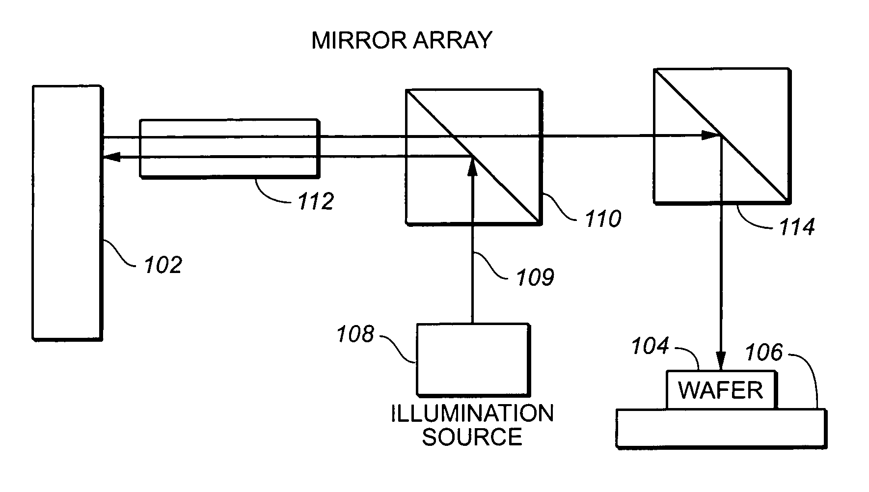
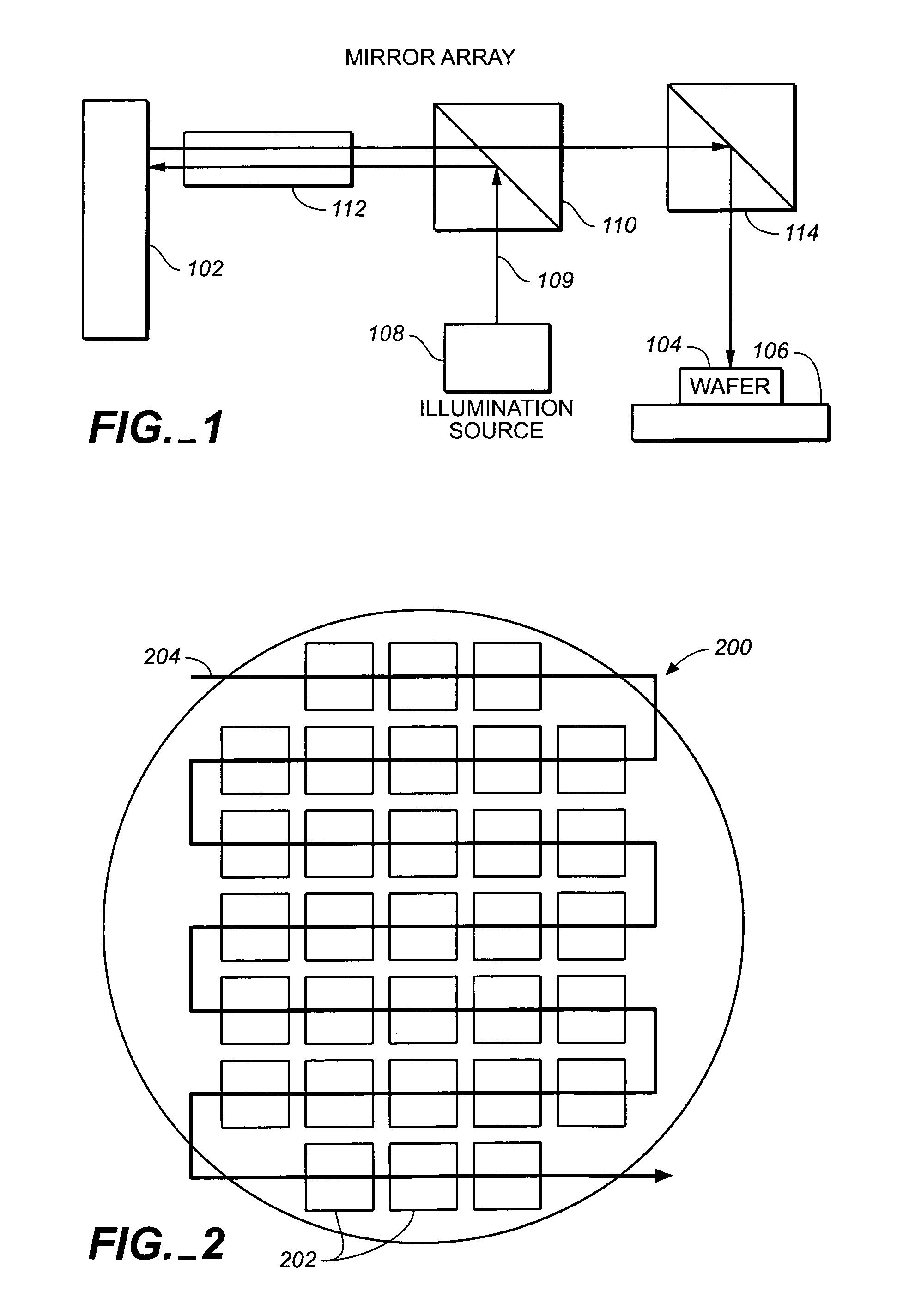
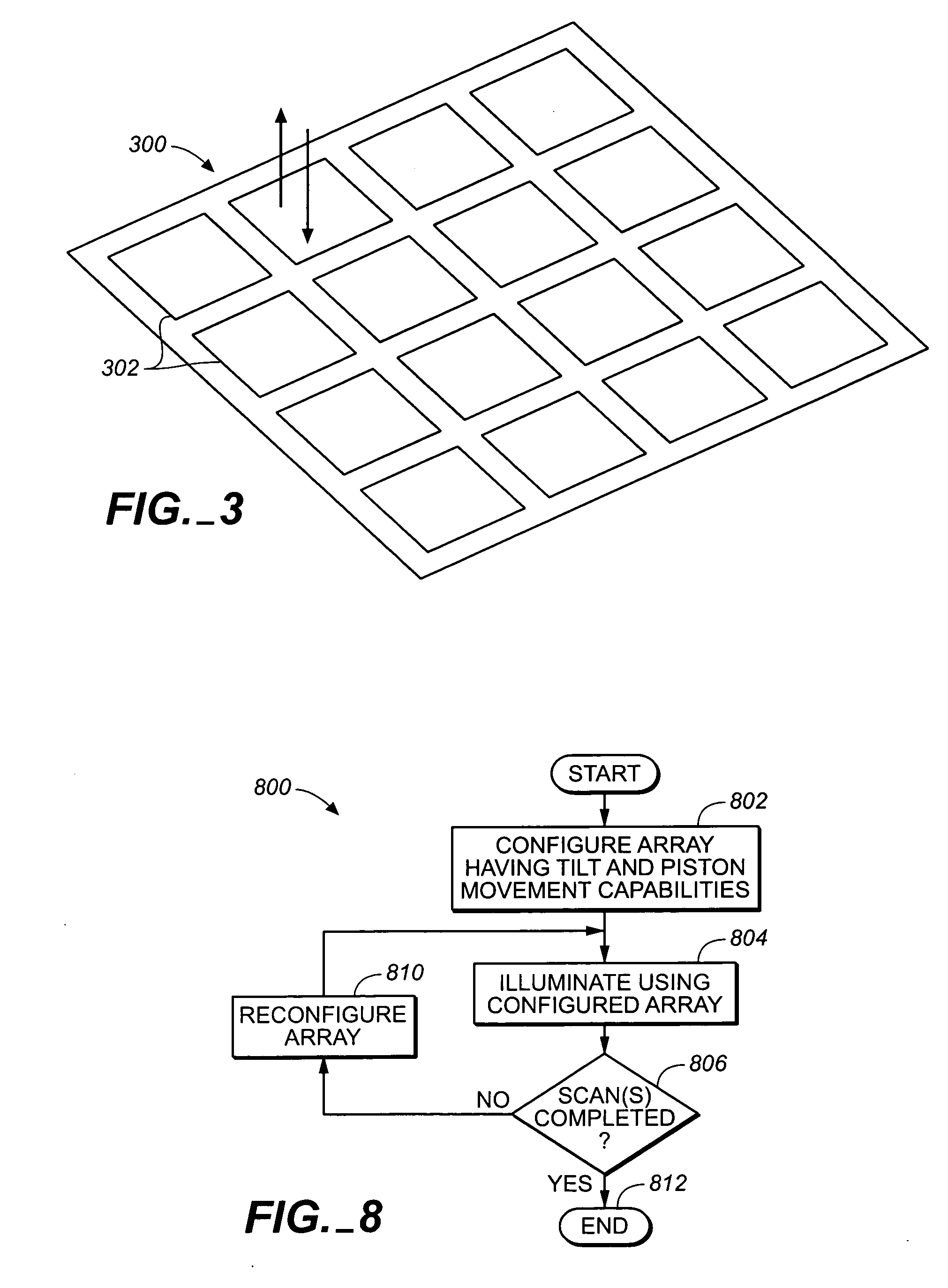
[0028] The present invention provides an optimized direct write lithography system...


PUM


Abstract

The present invention provides an optimized direct write lithography system using optical mirrors. That is, a maskless lithography system is provided. The maskless direct-write lithography system provided uses an array of mirrors configured to operate in a tilting mode, a piston-displacement mode, or both in combination. The controlled mirror array is used as a substitute for the traditional chrome on glass masks. In order to avoid constraining the system to forming edges of patterns aligned with the array of mirrors, gray-scale techniques are used for subpixel feature placement. The direct-writing of a pattern portion may rely on a single mirror mode or a combination of modes.

Description

CROSS-REFERENCE TO RELATED APPLICATIONS [0001] This application claims priority of U.S. Provisional Patent Application No. 60 / 513,780 (Attorney Docket No. 03-1810), filed 22 Oct. 2003, which application is incorporated herein by reference in its entirety for all purposes.BACKGROUND OF THE INVENTION [0002] 1. Field of the Invention [0003] The present invention relates to methods for forming semiconductor devices. More particularly, the present invention relates to methods for directly writing patterns to create semiconductor devices on semiconductor wafers. [0004] 2. Description of the Related Art [0005] Designers and semiconductor device manufacturers constantly strive to develop smaller devices from wafers, recognizing that circuits with smaller features generally produce greater speeds and increased packing density, therefore increased net die per wafer (numbers of usable chips produced from a standard semiconductor wafer). To meet these requirements, semiconductor manufacturers h...

Claims


Application Information

Patent Timeline
IPC IPC(8): G02B26/00G02B26/08G03F7/20
CPCG02B26/001G03F7/70291G03F7/70283G02B26/0833
Inventor EIB, NICHOLAS K.CROFFIE, EBOCALLAN, NEAL
Owner BELL SEMICON LLC
Why Eureka
Try Eureka