Method and apparatus for treatment by ionizing radiation

a technology of ionizing radiation and treatment method, applied in the field of ionising radiation treatment device, can solve the problem that the patient may not be cured, and achieve the effect of increasing the flexibility of treatmen

Active Publication Date: 2005-04-28
ELEKTA AB
View PDF12 Cites 89 Cited by
  • Summary
  • Abstract
  • Description
  • Claims
  • Application Information

AI Technical Summary

Benefits of technology

[0018] It is an object of the invention to provide a radiation therapy and / or surgery device thus optimised to meet the needs of the Neurosurgeon, i.e. for the treatment of pathological tissue in the brain or vicinity. It combines the qualities of a good penumbra and accuracy, simple prescription and operation, together with high reliability and minimal technical support.
[0027] The apparatus will generally include a patient support. It is preferred that the position of the patient support is adjustable, particularly under the control of the control means, with the control means being adapted to adjust that position in a manner correlated with the movement of the radiation source and / or the collimation thereof. This will allow increased flexibility in treatment.

Problems solved by technology

On the other hand, if the surviving cells are malignant they may continue to divide and the patient may not be cured.

Method used


Image

  • Method and apparatus for treatment by ionizing radiation
  • Method and apparatus for treatment by ionizing radiation
  • Method and apparatus for treatment by ionizing radiation

Examples


Embodiment Construction

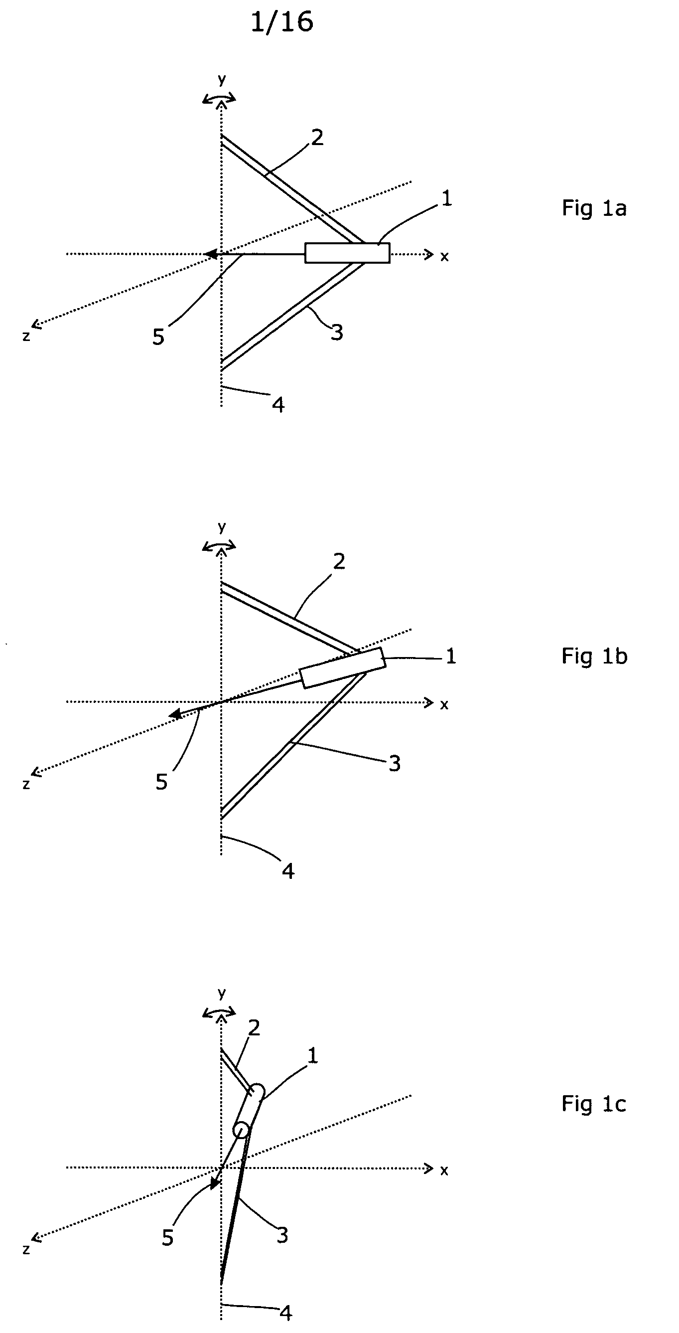
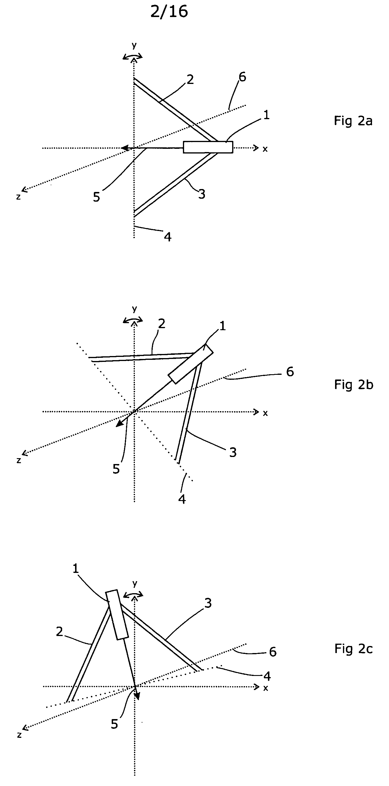
[0047]FIGS. 1a, 1b and 1c, together with FIGS. 2a, 2b and 2c, show the general principle of operation according to the present invention. They show that the geometry adopted by the invention constrains the radiation source such that a wide variety of approach angles are possible, but that the source can only point towards the isocentre.

[0048] Further, they illustrate how such an arrangement can be achieved using only rotateable joints. Thus, once the device is suitably supported or balanced around those joints, the problems inherent in the Nakagawa et al arrangement are avoided.

[0049] There are two main rotation axes according to the invention. FIGS. 1a, 1b and 1c show the effect of rotation about one of the axes, while FIGS. 2a, ab and 2c show the effect of rotation about the other. It is envisaged that, in practice, both axes would be used simultaneously.

[0050]FIG. 1a shows the device in a rest state in which a source 1 is supported by rigid members 2, 3 which are each attached...


PUM


Abstract

A radiation therapy / surgery device optimised to meet the needs of the Neurosurgeon is provided, i.e. one for the treatment of tumours in the brain. It combines the qualities of a good penumbra and accuracy, simple prescription and operation, together with high reliability and minimal technical support. The device comprises a rotateable support, on which is provided a mount extending from the support out of the plane of the circle, and a radiation source attached to the mount via a pivot, the pivot having an axis which passes through the axis of rotation of the support, the radiation source being aligned so as to produce a beam which passes through the co-incidence of the rotation axis and the pivot. It will generally be easier to engineer the apparatus if the rotateable support is planar, and more convenient if the rotateable support is disposed in an upright position. The rotation of the rotateable support will be eased if this part of the apparatus is circular. A particularly preferred orientation is one in which the radiation source is spaced from the rotateable support, to allow it to pivot without fouling the latter. It is thus preferred that the mount extends transverse to the support. In this way, the pivot axis is spaced from the rotateable support providing free space in which the radiation source can pivot. Another way of expressing this preference is to state that the pivot axis is located out of the plane of the rotateable support. To simplify the geometry of the device and the associated arithmetic, it is preferred both that the pivot axis is substantially perpendicular to the rotation axis, and that the beam direction is perpendicular to the pivot axis. It is preferred that the radiation source is a linear accelerator. The output of the radiation source is preferably collimated to conform to the shape of the area to be treated.

Description

FIELD OF THE INVENTION [0001] This invention relates to a device for treating a patient with ionising radiation. It is particularly suited to forms of radiosurgery and to certain forms of radiotherapy. BACKGROUND ART [0002] It is known that exposure of human or animal tissue to ionising radiation will kill the cells thus exposed. This finds application in the treatment of pathological cells. In order to treat tumours deep within the body of the patient, the radiation must however penetrate the healthy tissue in order to irradiate and destroy the pathological cells. In conventional radiation therapy, large volumes of healthy tissue can thus be exposed to harmful doses of radiation, resulting in prolonged recovery periods for the patient. It is, therefore, desirable to design a device for treating a patient with ionising radiation and treatment protocols so as to expose the pathological tissue to a dose of radiation, which will result in the death of these cells, whilst keeping the ex...

Claims


Application Information

Patent Timeline
Patent Type & Authority Applications(United States)
IPC IPC(8): A61N5/10
CPCA61N5/10A61N5/1082A61N5/1081A61N5/1042
Inventor BROWN, KEVIN JOHN
Owner ELEKTA AB
Why Eureka
Try Eureka