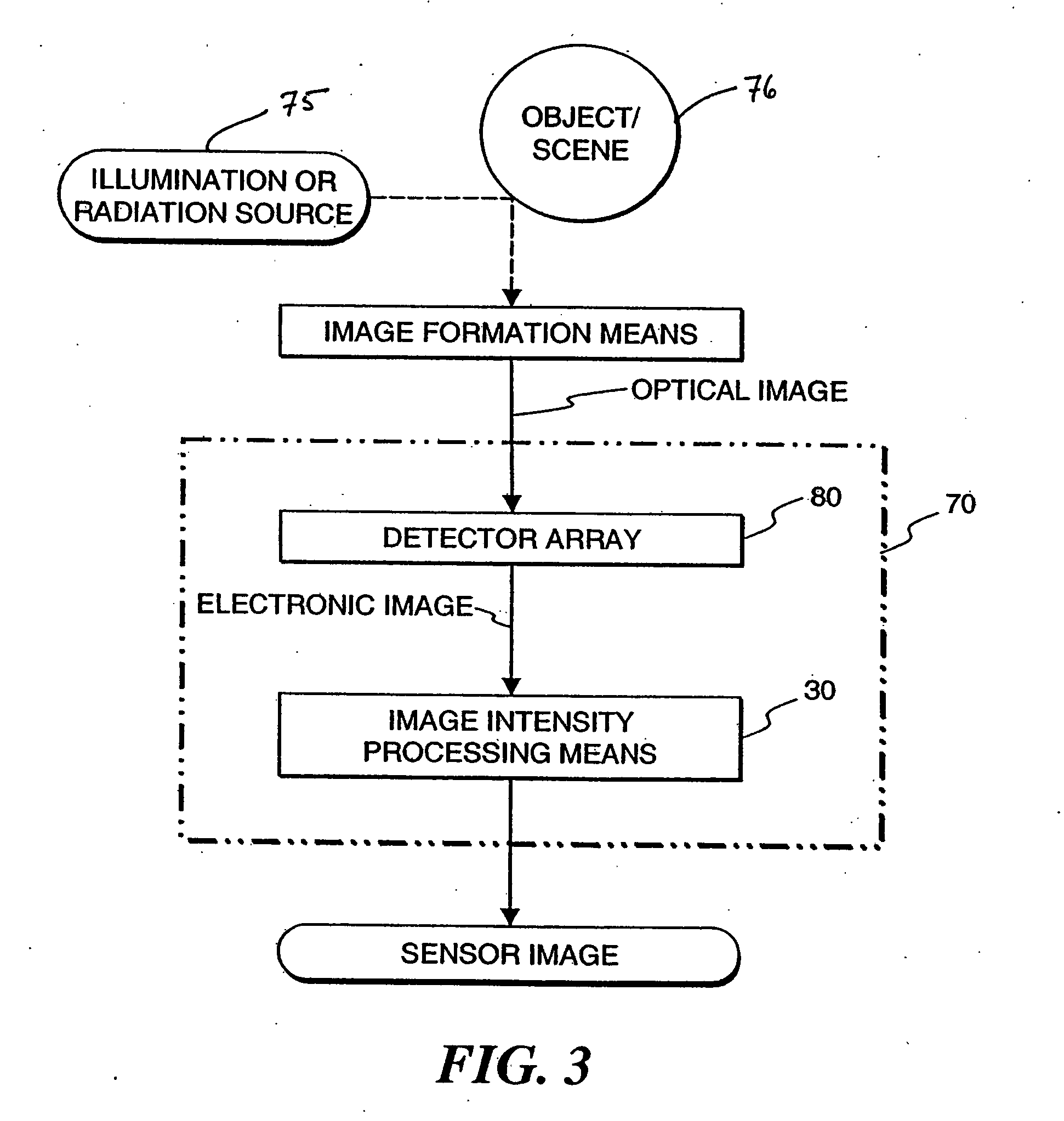
One problem with the present state of the art is that the dynamic range of natural optical images can easily exceed the available dynamic range of the imaging devices, the imaging devices either being photochemical emulsions / films / plates or electronic image sensors.
When such
high dynamic range optical images are received through the
image formation system (e.g., optical lens) and projected on the imaging media, the imaging media cannot easily sense such a high dynamic range
signal, resulting in
signal saturation and clipping in the sensed image.
There are numerous other examples where imaging fails due to limited dynamic range of imaging devices.
A
surveillance camera on a sunny day will normally report shadows as completely black and brightly illuminated surfaces as completely white, again limiting usefulness of the entire surveillance
system.
As these examples illustrate, the limited dynamic range problem of state-of-the-art imaging devices severely limits the usefulness of the entire imaging
system.
Another problem caused by dynamic range is mismatch of the
signal dynamic range of sensed images (e.g., film or electronic images) and the dynamic range available at a display or print medium.
The problem is how to render a high dynamic range image on a
low dynamic range display / print while showing all the details.
Clearly, a naive signal scaling would destroy some details due to quantization and / or signal clipping.
Furthermore, the illumination-induced variations (e.g., shadow patterns, and interreflections) may completely alter the appearance of an object in a scene.
Computer vision algorithms that often aim to recognize objects in a visual scene have difficulty accounting for all possible variations resulting in unreliable performance in real-world, unconstrained environments.
Humans are rarely fooled even when complicated illumination fields produce deep shadows and complicated patterns in the scene.
While this may be possible in some restricted industrial settings at great expense, it is not practical in many real-world situations where natural ambient illumination and general shape and arrangement of objects cannot be controlled.
Therefore, we are faced with the problem of estimating underlying object reflectance from
radiance maps.
Computing the reflectance and the
illuminance fields from real images is, in general, an ill-posed problem.
The halo artifact is a very objectionable artifact for human viewing.
In medical and automated
computer vision, halo artifacts could be misleading and potentially dangerous.
This method drastically reduces the dynamic range but tends to overemphasize fine details, thus still creating objectionable artifacts in the result.
The
algorithm is computationally intensive and requires the selection of no less than eight different parameters that need to be appropriately selected by a human user for a particular image.
These methods all suffer from producing halo artifacts around high-contrast edges.
The main drawback of bilateral and similar filtering is that it is very slow to compute.
Another drawback is that in some situations the result may require local corrections, which requires manually setting numerous parameters.
They cannot determine where the discontinuities occur in the input and will tend to blur across them.
As discussed earlier, blurring across large discontinuities is not desirable, as it will produce objectionable halos.
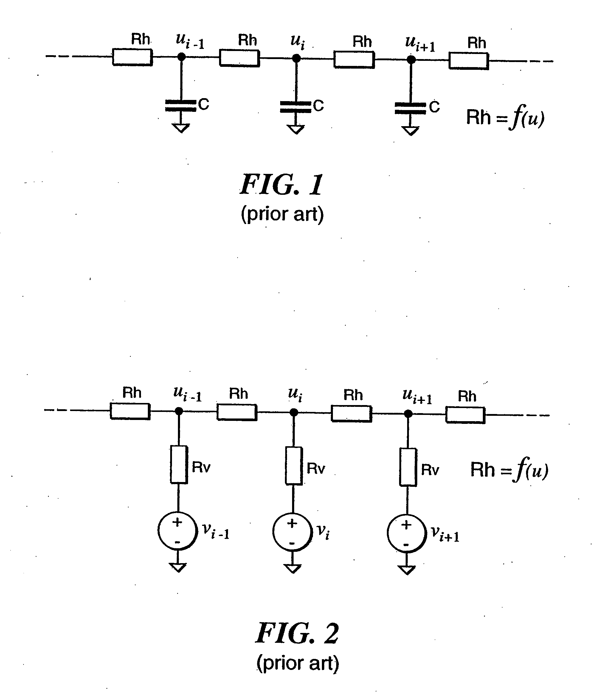
The current through a saturating horizontal
resistor will saturate as the
voltage across the
resistor becomes large, thus not smooth as much for large discontinuities.
There are at least three problems associated with previously proposed discontinuity preserving
smoothing resistive networks.
The first problem is that the presence or absence of a discontinuity in the input image v(x) is judged based on the smoothed result u(x).
Therefore, the horizontal resistors that adjust their resistances as a function of their terminal voltages (e.g., Rh=f(u)) may not be able to appropriately capture discontinuities present in the input image.
The second problem is that the circuit designer is left with a difficult task of creating nonlinear resistors whose resistivity changes with the
voltage drop across its terminals.
These functions approximate desired behavior but may not be the most optimal choice from the mathematical point of view.
The third problem is that when the network is to be solved numerically, the nonlinear
resistive element requires iteration.
This iterative process is numerically involved and still suffers from the problem that the presence or absence of discontinuities is judged based on the smoothed image.

