
Cancellation of transmitted signal crosstalk in optical receivers of diplexer-based fiber optic transceivers

Inactive Publication Date: 2005-04-28
REGEV ZVI +1
View PDF12 Cites 27 Cited by
  • Summary
  • Abstract
  • Description
  • Claims
  • Application Information

AI Technical Summary

Benefits of technology

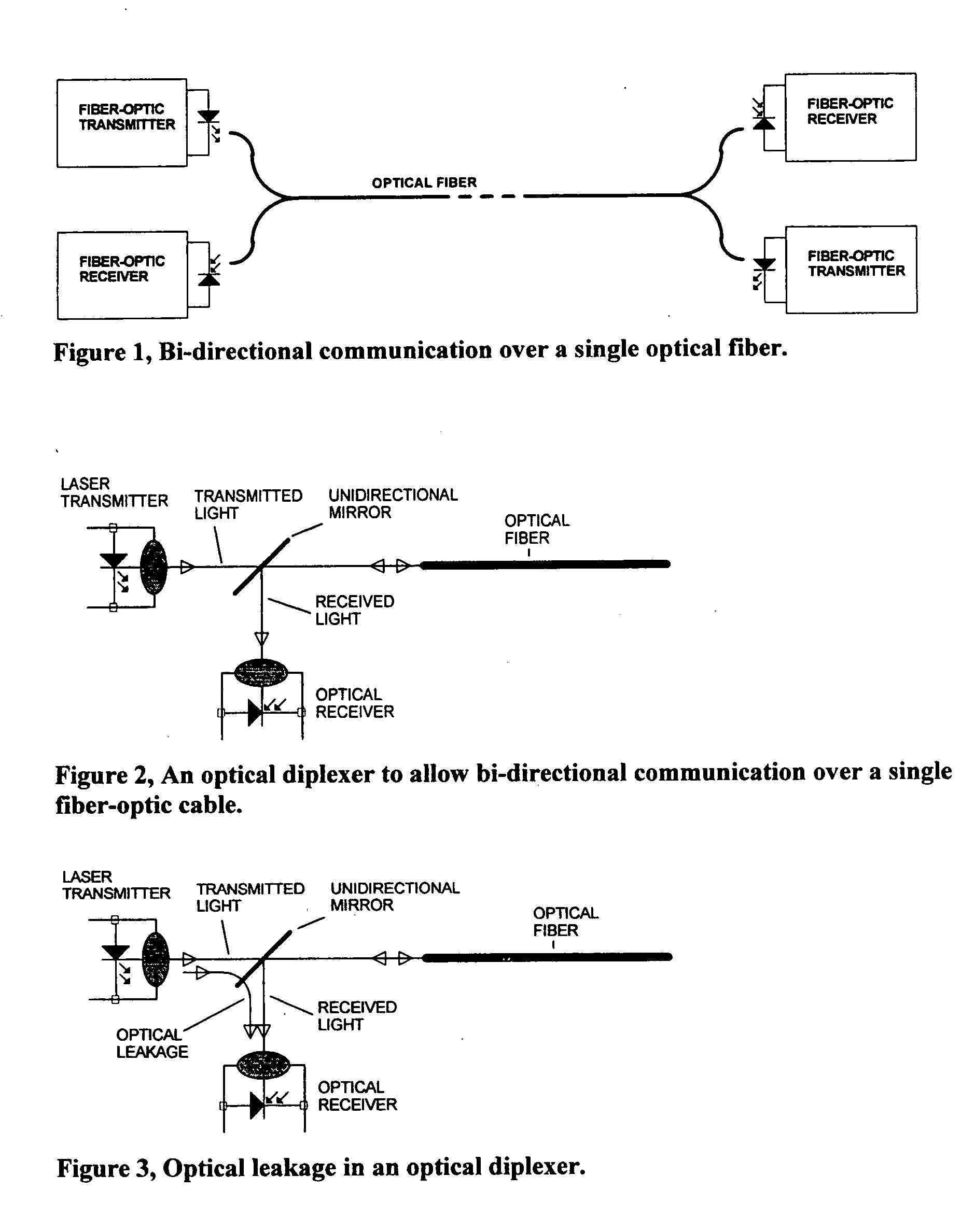
[0007] Signals transmitted over optical fibers are typically high frequency in nature, and typically the lowest frequency transmitted is in the order of several hundreds of megahertz. Lower frequency signals can thus be used to control the crosstalk cancellation. To minimize the effect of the marker signal on the transmitted or the received signals, and to allow easy identification of the marker, this marker signal also known a pilot signal must occupy a very small frequency bandwidth. To enable independent monitoring on the effects of the phase, and the magnitude adjustments, the pilot signal is to contain two signals, which are exclusively independent, such as two sine waves of harmonically independent frequencies.
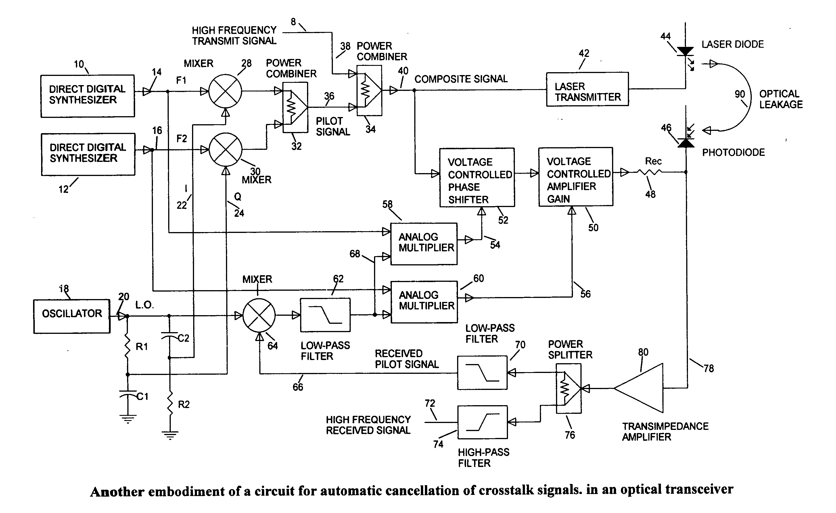
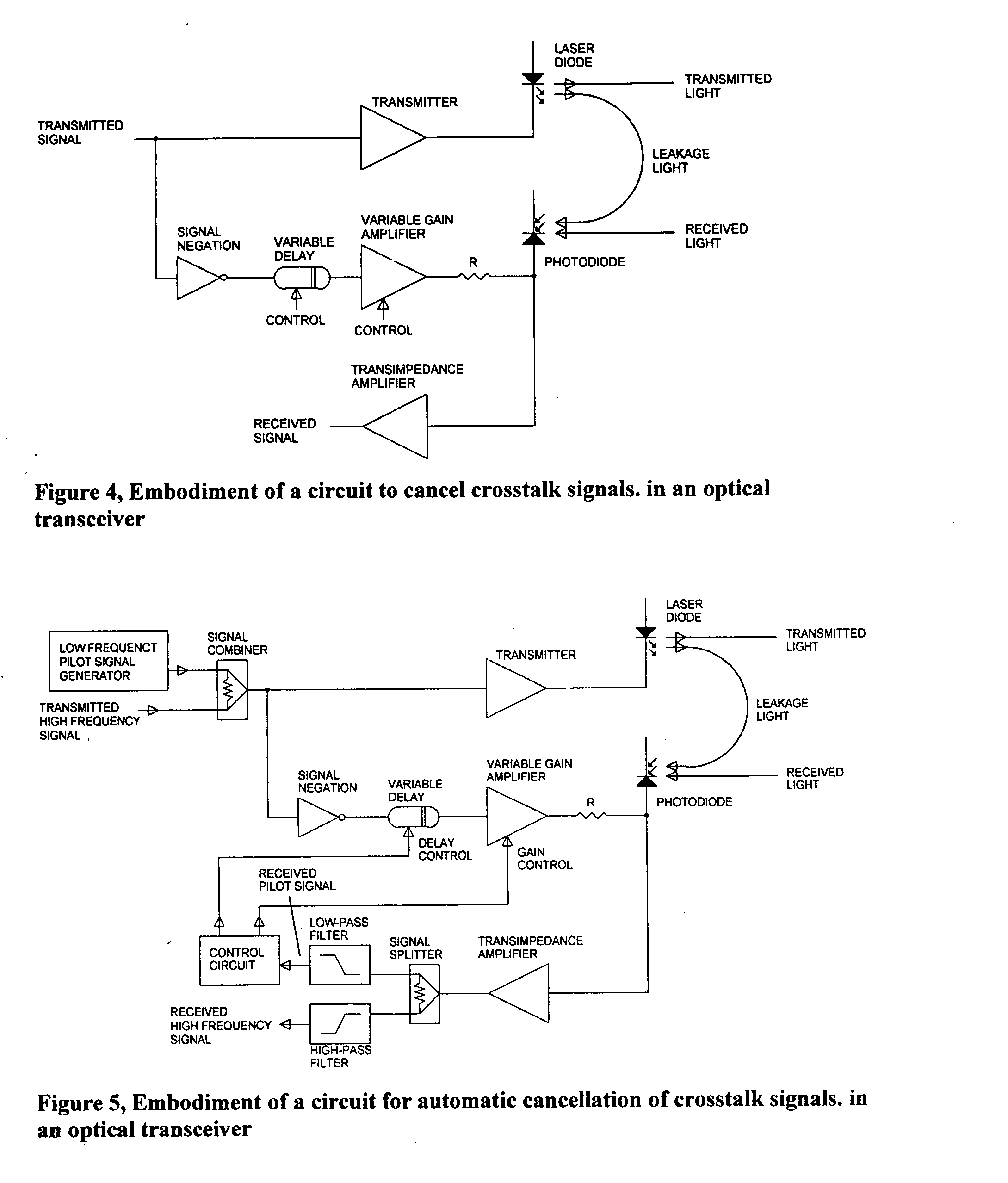
[0008] Having a pilot signal transmitted along with the normally transmitted high frequency signals, allows automatic control over the crosstalk cancellation process, as shown in FIG. 5. To independently control the phase and the magnitude, two special low frequency signals are generated and combined as a pilot signal and transmitted along with the high frequency signals over the optical fiber. The signals received in the receiver are comprised of the high frequency signals, the high frequency crosstalk signals, and the low frequency pilot signal. It is assumed that the frequency bandwidth of the transceiver is very large, and therefore the pilot signal, transmitted along with the high frequency signals is delayed through the transmitter exactly the same delay as the high frequency signals. In the receiver the pilot signal can be separated from the high frequency crosstalk signal simply by means of a low pass filter, as shown in FIG. 5. The two components of the pilot signal are completely independent of each other, and each has some unique properties so that it can be readily separated and used independently. One signal is used in a phase locked loop, comprised of the variable phase shifter, the variable gain amplifier, the series resistor, the optical receiver, and the low-pass filter, to control the delay in the variable delay device to achieve precise 180° phase shift in the canceling signal path. The other signal is used in a peak detector to measure the magnitude of that signal at the output of the receiver. The output of the peak detector is used to control the gain of the variable gain amplifier, and the magnitude of the canceling signal current, such that the magnitude of the pilot signal at the peak detector is minimized.

Problems solved by technology

This method of transmission is problematic, however.

Method used


Image

  • Cancellation of transmitted signal crosstalk in optical receivers of diplexer-based fiber optic transceivers
  • Cancellation of transmitted signal crosstalk in optical receivers of diplexer-based fiber optic transceivers
  • Cancellation of transmitted signal crosstalk in optical receivers of diplexer-based fiber optic transceivers

Examples


Embodiment Construction

[0005] Intuitively, cancellation of undesired signals is possible by a summation of the unwanted signal, and another signal identical to the unwanted signal, but shifted in phase by 180°. Since both the laser transmitter, and the receiver affected by the crosstalk are housed in the same module, the signals transmitted by the laser transmitter, and eventually are leaking into the receiver and causing the crosstalk are known and available. Hence the received signal, which contains some signals that have leaked from the transmitter, can be summed up with the inverse of a sample of the transmitted signal. For full cancellation, the sample of the transmitted signal must be exactly the same magnitude as the magnitude of the leaked signal embedded in the received signal. The sample of the transmitted signal must also be phase shifted by exactly 180° with respect to the received crosstalk signal. In the circuit shown in FIG. 4, a sample of the transmitted signal is negated, converted into c...


PUM


Abstract

Methods and devices for minimizing the crosstalk induced by optical leakage within fiber-optic transceivers are provided. Methods of the invention include wherein a pilot signal is generated and transmitted along with the other signals, and then used as a reference for evaluating the parameters of crosstalk when it occurs. The pilot signal is recognized and extracted from the received signals to manage control the process of crosstalk cancellation. Thus, when crosstalk occurs, samples of the transmitted signal are subtracted from the received signal so as to cancel out any residue of the transmitted signal found in the received signal.

Description

RELATED APPLICATIONS [0001] The present application claims priority to U.S. Provisional Application No. 60 / 507,968, filed Oct. 3, 2003. The cited Application is hereby incorporated by reference in its entirety.FIELD OF THE INVENTION [0002] This invention deals with crosstalk cancellation in communication channels, and in particular with crosstalk commonly induced by transmitted signals on optical receivers in optical diplexer-based fiber-optic transceivers. BACKGROUND OF THE INVENTION [0003] High-speed signals are transmitted over fiber optic cables mainly because of the unique properties of the fiber-optic transmission medium, namely the inherent wide band of data transmission, and low attenuation through the fiber. Signals are transmitted over an optical fiber typically by means of amplitude modulation of a light wave carrier. [0004] To save cost in installations, optical fibers are often utilized in bi-directional transmission over a single fiber, wherein optical signals are simu...

Claims


Application Information

Patent Timeline
IPC IPC(8): H04B10/02H04B10/08H04B10/18
CPCH04B10/0775H04B2210/075H04B10/2543
Inventor REGEV, ZVIMARGALIT, SCHLOMO
Owner REGEV ZVI
Learn More