Catheter having a multilayered shaft section with a reinforcing mandrel

a multi-layered, reinforcing mandrel technology, applied in the field of catheters, can solve the problems that the support mandrel does not always transmit axial force effectively, prior art designs have suffered from various drawbacks, etc., and achieve excellent pushability, trackability, and manufacturability.

Inactive Publication Date: 2005-04-28
DUCHAMP JACKY G
View PDF8 Cites 9 Cited by
  • Summary
  • Abstract
  • Description
  • Claims
  • Application Information

AI Technical Summary

Benefits of technology

[0007] In a presently preferred embodiment, the multilayered section of the shaft with the first and second layers is a proximal shaft section. In one embodiment, the first layer has a distal end located proximal to the distal end of the second layer, and the shaft has a distal shaft section comprising a distal section of the second layer extending beyond the first layer distal end. The multilayered proximal shaft section is typically about 50 to about 80% of the length of the catheter shaft. In a presently preferred embodiment, the section of the mandrel between the first and second layers is a proximal section, so that the mandrel has a proximal section secured between and in contact with the first and second layers from the proximal to the distal end of the first layer, and a distal section extending beyond the distal end of the first layer. The distal section of the mandrel extending beyond the distal end of the first layer is typically about 10 to about 40%, preferably about 20 to about 30% of the mandrel length. Alternatively, the mandrel has a distal end section located between and in contact with the first and second layers, so that in one embodiment, the entire length or at least substantially all of the length of the mandrel is located between the first and the second layers. With the reinforcing mandrel secured between the first and second layers and optionally extending beyond the end of the first layer, the catheter shaft provides improved pushability and kink resistance. Preferably, the catheter distal shaft section is relatively flexible and soft and the proximal shaft section is relatively stiff and pushable, without requiring separate longitudinal segments joined together. Thus, it should be understood that the proximal shaft section and the distal shaft section may be formed of a unitary, one piece tubular member, as for example in the embodiment in which the shaft comprises a multilayered proximal shaft section formed of the first layer secured to a surface of the second layer, and a distal shaft section formed of the portion of the second layer which extends beyond the distal end of the first layer. Consequently, the catheter of the invention has excellent pushability, trackability, and manufacturability, and preferably without external or internal junctions between longitudinal segments.
[0011] The catheter of the invention is highly pushable, flexible, trackable and kink resistant due to the reinforcing mandrel secured between the first and second layers of the shaft. The shaft of the invention provides an improved transition between the proximal shaft section and the more flexible distal shaft section, for improved kink resistance. Thus, the flexible and pushable shaft provides a catheter with excellent trackability, and allows easy advancement over a guidewire and maneuvering within the patient's tortuous anatomy, to position the operative portion of the catheter at a desired location within the patient. These and other advantages of the invention will become more apparent from the following detailed description of the invention and the accompanying exemplary drawings.

Problems solved by technology

Despite these attempts, prior art designs have suffered from various drawbacks.
For example, support mandrels do not always transmit axial force effectively.

Method used


Image

  • Catheter having a multilayered shaft section with a reinforcing mandrel
  • Catheter having a multilayered shaft section with a reinforcing mandrel
  • Catheter having a multilayered shaft section with a reinforcing mandrel

Examples


Embodiment Construction

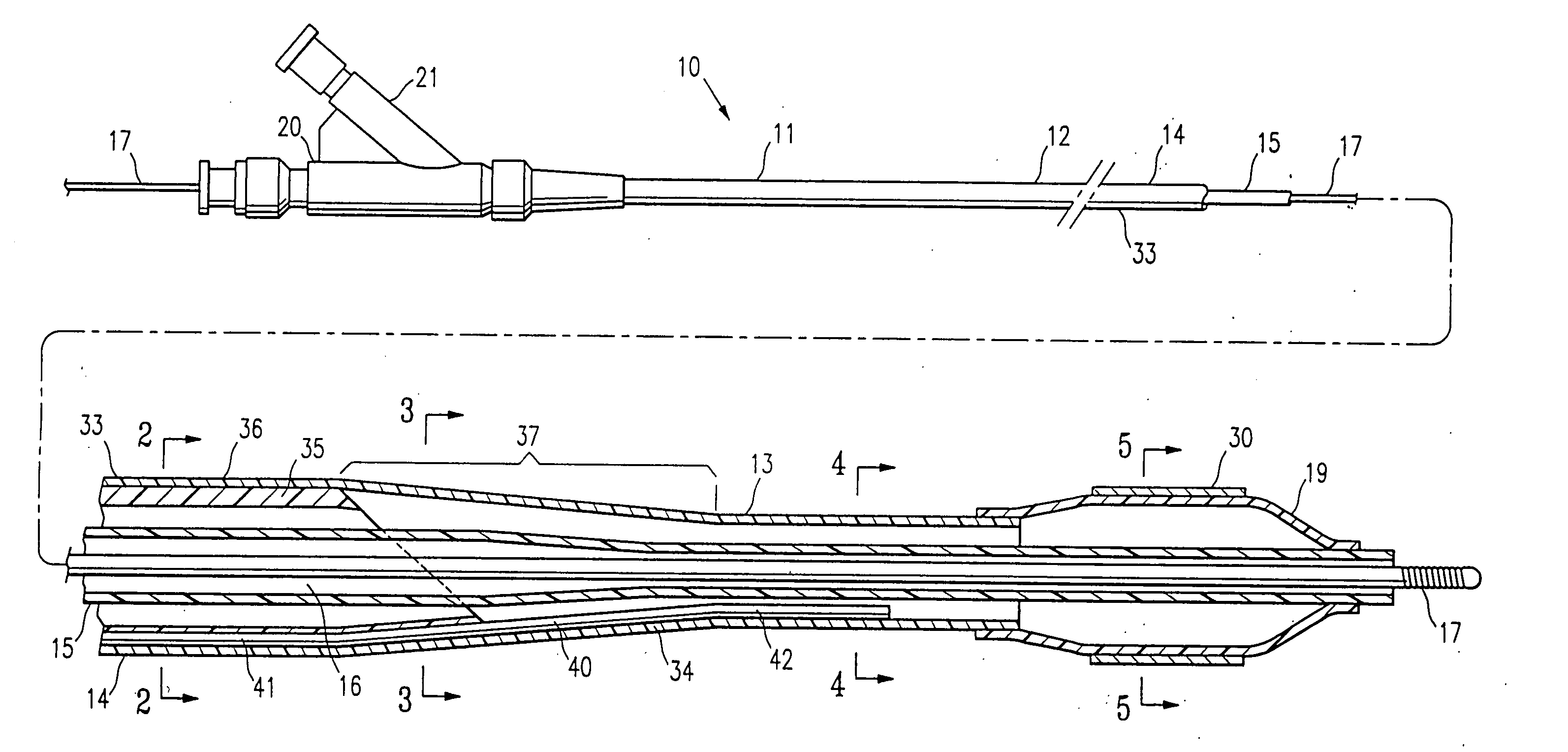
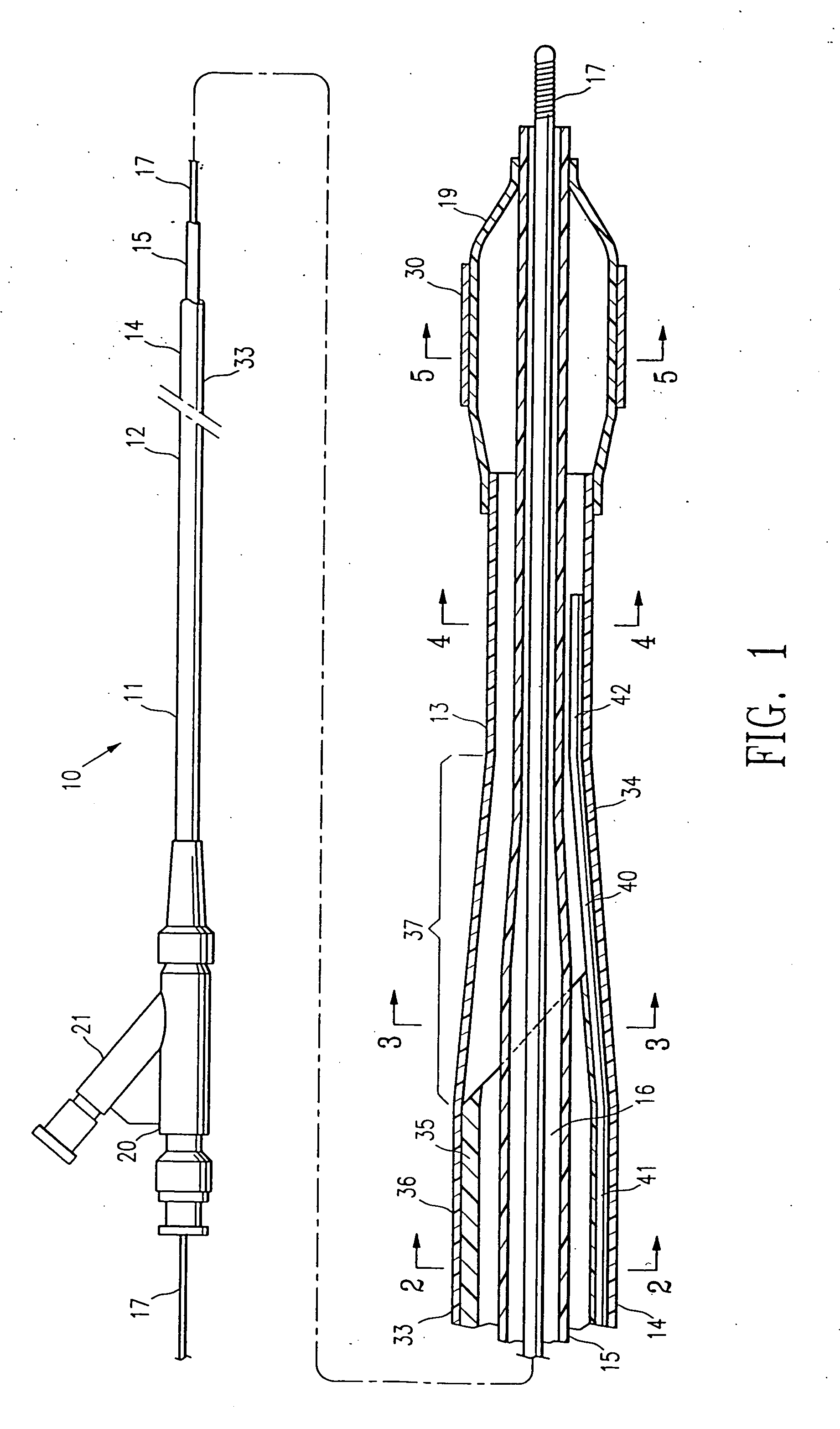
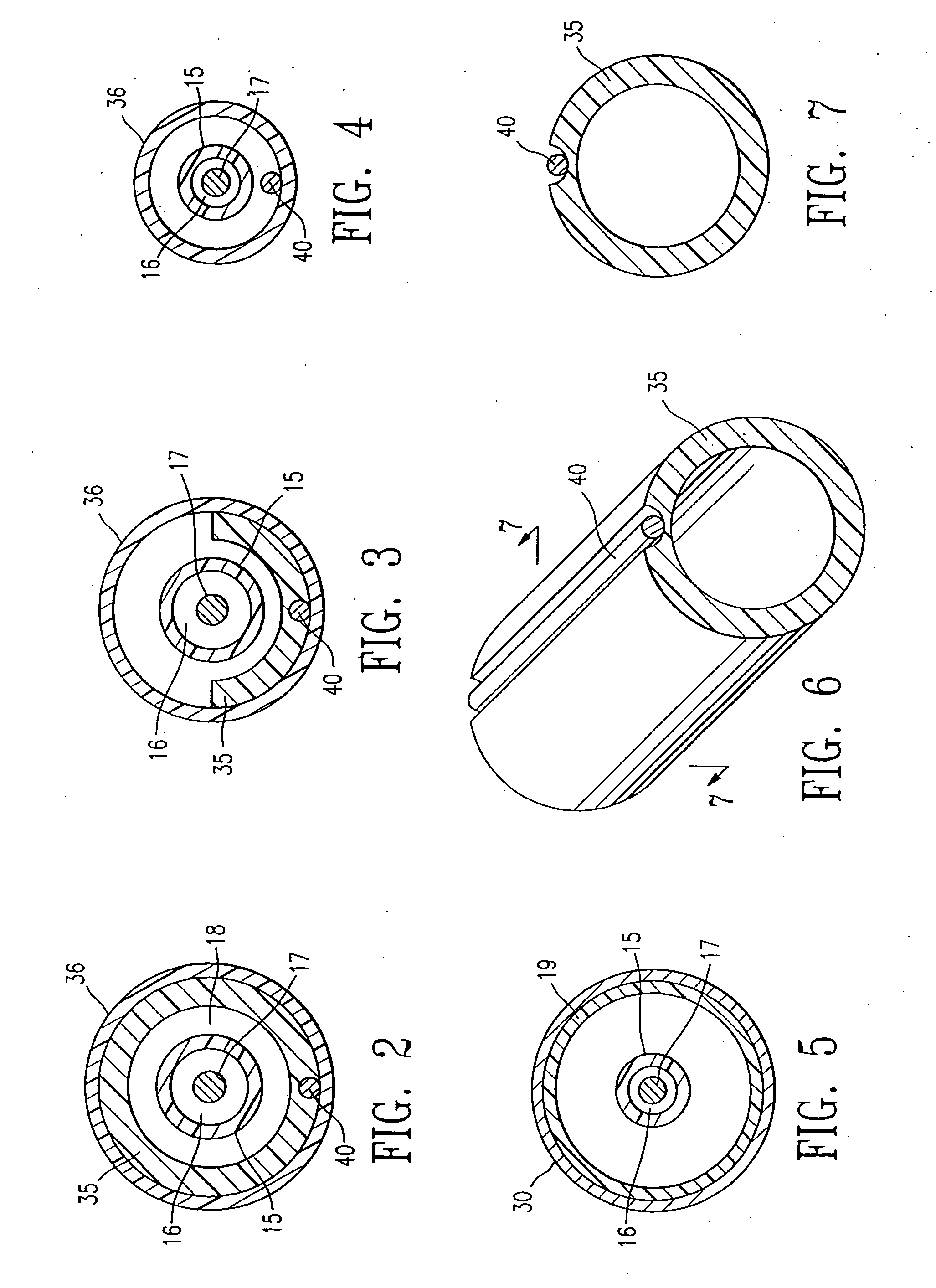
[0019]FIG. 1 illustrates an over-the-wire balloon catheter 10 embodying features of the invention. Catheter 10 generally comprises an elongated catheter shaft 11 having a proximal end, a distal end, a proximal shaft section 12, a distal shaft section 13, an outer tubular member 14, and an inner tubular member 15. Inner tubular member 15 defines a guidewire lumen 16 adapted to slidingly receive a guidewire 17. The coaxial relationship between outer tubular member 14 and inner tubular member 15 defines annular inflation lumen 18, as best shown in FIGS. 2-4, illustrating transverse cross sections of the catheter of FIG. 1, taken along lines 2-2, 3-3 and 4-4, respectively. An inflatable balloon 19 is disposed on the distal shaft section 13, having a proximal skirt section sealingly secured to the distal end of outer tubular member 14, and a distal skirt section sealingly secured to the distal end of inner tubular member 15, so that its interior is in fluid communication with inflation l...


PUM


Abstract

A catheter having an elongated shaft having at least a section which is multilayered with a first layer and a second layer secured to the first layer, and a mandrel having at least a section between the first and second layers. In one presently preferred embodiment, the mandrel is in contact with an outer surface of the first layer and with an inner surface of the second layer.

Description

BACKGROUND OF THE INVENTION [0001] This invention generally relates to catheters, and particularly intravascular catheters for use in percutaneous transluminal coronary angioplasty (PTCA) or for the delivery of stents. [0002] In percutaneous transluminal coronary angioplasty (PTCA) procedures a guiding catheter is advanced in the patient's vasculature until the distal tip of the guiding catheter is seated in the ostium of a desired coronary artery. A guidewire is first advanced out of the distal end of the guiding catheter into the patient's coronary artery until the distal end of the guidewire crosses a lesion to be dilated. A dilatation catheter, having an inflatable balloon on the distal portion thereof, is advanced into the patient's coronary anatomy over the previously introduced guidewire until the balloon of the dilatation catheter is properly positioned across the lesion. Once properly positioned, the dilatation balloon is inflated with inflation fluid one or more times to a...

Claims


Application Information

Patent Timeline
Patent Type & Authority Applications(United States)
IPC IPC(8): A61F2/958A61M25/00
CPCA61M25/005A61M25/0053Y10T428/13A61M2025/0063A61M2025/1086A61M25/10
Inventor DUCHAMP, JACKY G.
Owner DUCHAMP JACKY G
Why Eureka
Try Eureka