Implantable, self-expanding prosthetic device

a prosthetic device and self-expanding technology, applied in the field of implantable medical devices, can solve the problems of reducing or completely losing the functional attributes of the device, unable to withstand only limited external compression forces, and further loss of frame stiffness

Inactive Publication Date: 2005-04-28
KAVTELADZE ZAZA A +4
View PDF5 Cites 40 Cited by
  • Summary
  • Abstract
  • Description
  • Claims
  • Application Information

AI Technical Summary

Benefits of technology

[0033] The invention is based on the problem of creating a device for sustaining a vessel or hollow organ lumen, in which the shape and arrangement of cells forming the tubular frame provide the frame with a large stiffness in the radial direction and only low stiffness in the axial direction so that the device without risk of traumatization will keep the vascular or hollow organ open, even if the latter changes shape due to external loads.

Problems solved by technology

Various diseases of blood vessels or hollow organs cause a stenosis or complete obturation (occlusion) of their lumen, which results in a decrease or complete loss of their functional attributes.
The problem of designing such devices has already a twenty year history.
Nevertheless, a universally reliable device satisfying all necessary requirements has as yet not been created.
Furthermore, the device can withstand only limited external compression forces.
The use of the known device in vessels and hollow organs with a diameter exceeding 8 mm, and without exceeding the ultimate strain of the frame material, would demand a decrease of the thickness of the wire frame elements, which would result in a further loss of stiffness of the frame.
Alternatively, it would be necessary to increase the diameter of the puncture hole, which in turn would cause intolerable trauma to the vascular or hollow organ walls.
However, the making of the frame with a minimum lead between coils results in a loss of its stiffness in the vessel or hollow organ.
In the process of uncoiling, which is uncontrolled, trauma to the vascular or hollow organ walls may occur, which has an unfavorable affect on the result of operation.
In addition, the frame can occupy an arbitrary position in the vessel that is uncontrolled by the surgeon.
The use of this device in arterial vessels is hardly possible because of the large distances between the wire elements, which may result in germination of atherosclerotic patches and, as a consequence, in an ineffective use of this device.
However, the loss in diameter thickness may hardly provide an effective means for sustaining the lumen.
Due to the arrangement of the wire branches in the peripheral direction of the tubular frame body, the given construction is stable and has a high stiffness in the axial direction, which prevents full adjustment of the vessel geometry and may traumatize the vascular or hollow organ walls.
When it is necessary to deliver the above device to the affected area along a curved path, the elastic deformation of the frame wire elements changes into plastic deformation, which results in an irreversible change of the device shape.
However, the use of a rigid joint by fusing together, soldering or welding of the wire elements in the points of their intersection seems to be unreliable because of: a probable proceeding of electrochemical processes in the soldering zone, which may cause damage to the joint, loss of stiffness in the frame and consequently, loss of its functional attributes; and formation of the so-called welding zone with an embrittled material structure, which may make this joint unreliable.
When it is necessary to deliver the device to the affected area along a curved path, a danger arises to exceed the ultimate elastic strain and, consequently, the proceeding of the process of plastic deformation of the frame material.
Thus, the delivery of the given frame is possible only along a path close to a straight line, which essentially decreases the possibility of its use in different anatomic areas.
The known device has a large stiffness in the axial direction which may traumatize the walls of the vascular or hollow organ in the regions around the ends of the device if the device supports a vascular or hollow organ which changes its shape during adaptation to varying external loads.
Further, it is a common disadvantage of the known devices that they possess limited radial stiffness, which allows them to support only vascular or hollow organs that are not surrounded by a bone structure taking up external loads.

Method used


Image

  • Implantable, self-expanding prosthetic device
  • Implantable, self-expanding prosthetic device
  • Implantable, self-expanding prosthetic device

Examples


Embodiment Construction

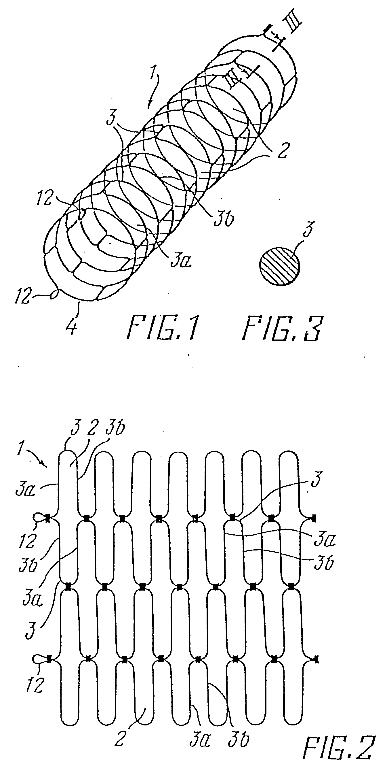
[0053] The device for sustaining the lumen, for example of the femoral artery, accomplished in accordance with the invention, has wire frame 1 in the form of a tubular shaped body such as a hollow cylindrical body.

[0054] The cylindrical surface of frame 1 shown in development in FIG. 2 is formed by a large number of interconnected cells 2 formed by two U-shaped wire sections 3, interconnected by their branches 3a, 3b, and forming approximately an oval, whose larger axis is arranged in the circumferential direction of the body and the smaller axis parallel to its axial direction. Cell 2 of each subsequent row is shifted in the circumferential direction with respect to cell 2 of the present row by ½ of the length of the oval larger axis. Each branch 3a or 3b of the U-shaped wire section 3 belongs to two cells 2 in adjacent rows, except for the first and last rows. In a cross-section of frame 1 in a plane perpendicular to its longitudinal axis and passing through the long branches of ...


PUM


Abstract

A prosthetic device for sustaining a vessel or hollow organ lumen (a stent) has a tubular wire frame (1) with rows of elongate cells (2) having a larger axis and a smaller axis. The cells are arranged with the larger axis in the circumferential direction of the frame (2) and the smaller axis parallel to the axial direction thereof. Each cell is formed by two U-shaped wire sections, and in a plane perpendicular to the longitudinal axis one of the branches of the U-shaped wire sections in one row form together a closed ring shape (4) which provides the frame (1) with large radial stiffness. In the axial direction the frame (1) has only low stiffness so that it easily conforms to the vascular wall even if this deforms due to external loads. The interconnection between the cells (2) may be flexible.

Description

CROSS-REFERENCE TO RELATED APPLICATIONS [0001] This application is a continuation-in-part of copending U.S. Design Patent Application Ser. No. 29 / 034,346, filed Feb. 2, 1995, entitled “An Implantable, Self-Expanding Stent” and commonly assigned herewith, which application is a continuation-in-part of U.S. Utility Patent Application Ser. No. 08 / 379,582, filed Feb. 1, 1995, entitled “A Prosthetic Device for Sustaining a Blood Vessel or Hollow Organ Lumen,” which application is the U.S. national phase of International Patent Application No. PCT / DK93 / 00256, filed Aug. 6, 1993, which application claims priority to Russian Application No. 5057852, filed Aug. 6, 1992 (now Reg. No. 35-13-426, granted Feb. 18, 1993).TECHNICAL FIELD [0002] The invention pertains to implantable medical devices and, in particular, to a self-expanding prosthetic device for sustaining a vessel or hollow organ lumen. BACKGROUND OF THE INVENTION [0003] Various diseases of blood vessels or hollow organs cause a sten...

Claims


Application Information

Patent Timeline
Patent Type & Authority Applications(United States)
IPC IPC(8): A61F2/00A61F2/90
CPCA61F2/90A61F2/95A61F2210/0019A61F2002/9511A61F2002/9665A61F2002/9505
Inventor KAVTELADZE, ZAZA A.KORSHOK, ALEKSANDR P.KADNIKOV, ANDREJ A.HANSEN, PALLEKIRTS, BETH ANN
Owner KAVTELADZE ZAZA A
Why Eureka
Try Eureka