Performance in model-based OPC engine utilizing efficient polygon pinning method

a polygon pinning and model-based technology, applied in the field of optical lithography, can solve the problems of requiring a significant amount of memory, and a critical part of the model, and achieves the effect of reducing the number of data structures and numerical overhead, reducing computational time, and facilitating and cost-effective convoluted polygons

Inactive Publication Date: 2005-04-28
GLOBALFOUNDRIES INC
View PDF6 Cites 42 Cited by
  • Summary
  • Abstract
  • Description
  • Claims
  • Application Information

AI Technical Summary

Benefits of technology

[0021] It is another object of the present invention to provide a polygon pinning method that accurately, efficiently, easily and cost effectively convolutes polygons within a region of interest.
[0022] A further object of the invention is to provide a polygon pinning method that reduces the number of data structures and the numerical overhead in a sector based OPC calculation.
[0023] Another object of the invention is to provide a polygon pinning method that saves computation time by increasing the rate of convolving polygons within a R

Problems solved by technology

Since present lithographic tools employ partially coherent illumination, such modeling is computationally intensive for all but elementary patterns.
However, the short and intermediate range is a critical part that can be time consuming due to the need to address individual polygons.
However, conventional sector based OPC calculations are often time consuming and require a significant amount of memory as calculations are performed for each sector within the square region of interest (ROI) 10 and then stored in the tables (matrices) for later use.
In addition to the above, sector based OPC calculations also suffer from accuracy deficiencies for certain long-range kernel.
That is, mathematical difficulties arise in optical proximity correction calculations that, in part, can be attributed to divergence issues when attempting to analytically express imaging kernels over the unbound sectors, of which mask polygons are conventionally decomposed.
However, in so doing, a disadvantage is that any points lying outside the radius relative to the vertex of the skewed ROI 10′, as is depicted by the arrow in FIG. 2B, are outside of the pre-calculated matrix, and therefore, will not add any contribution to convolution of the polygon.
The larger lookup table ROI 15 is

Method used


Image

  • Performance in model-based OPC engine utilizing efficient polygon pinning method
  • Performance in model-based OPC engine utilizing efficient polygon pinning method
  • Performance in model-based OPC engine utilizing efficient polygon pinning method

Examples


Embodiment Construction

)

[0049] In describing the preferred embodiment of the present invention, reference will be made herein to FIGS. 1-5 of the drawings in which like numerals refer to like features of the invention.

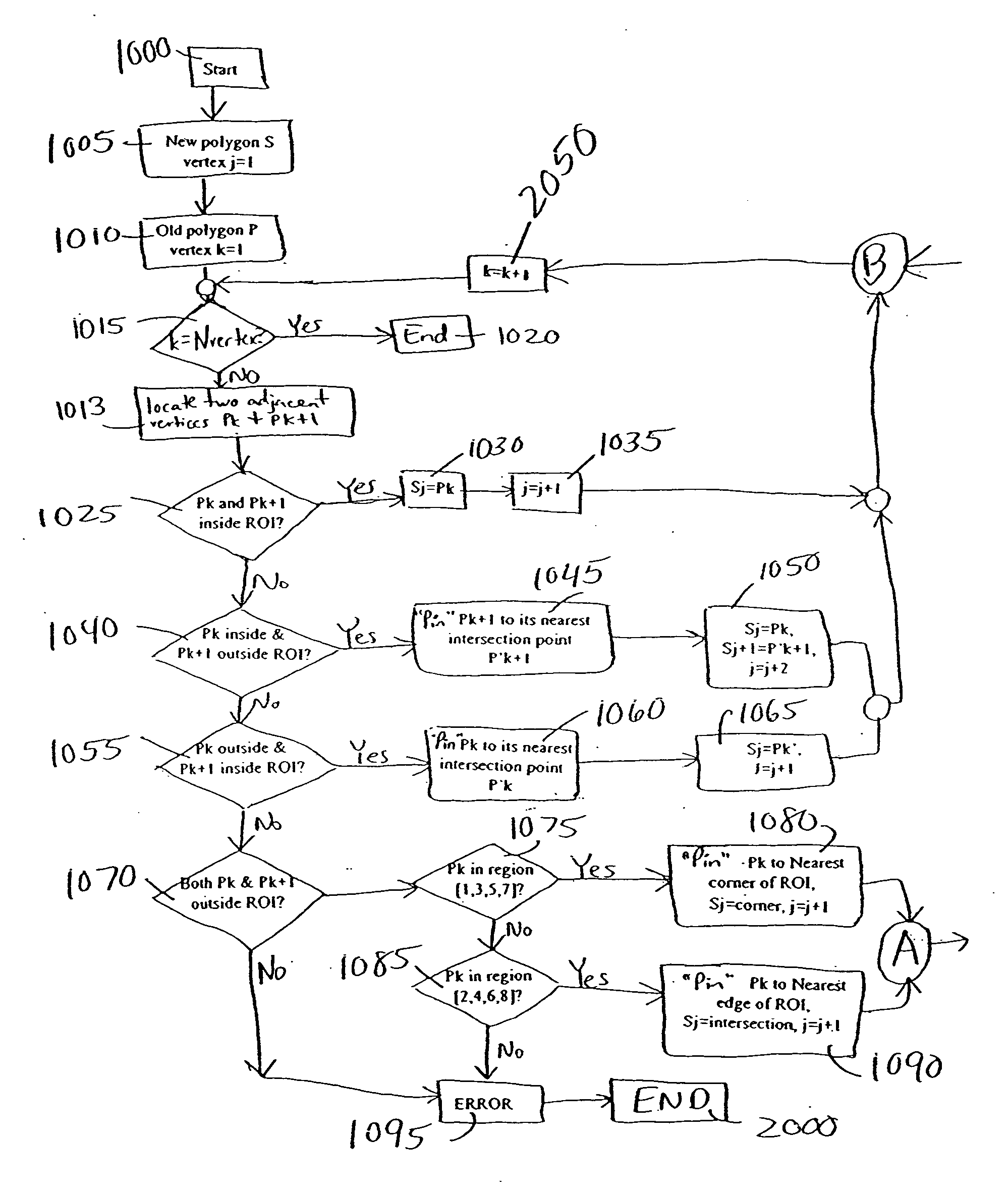
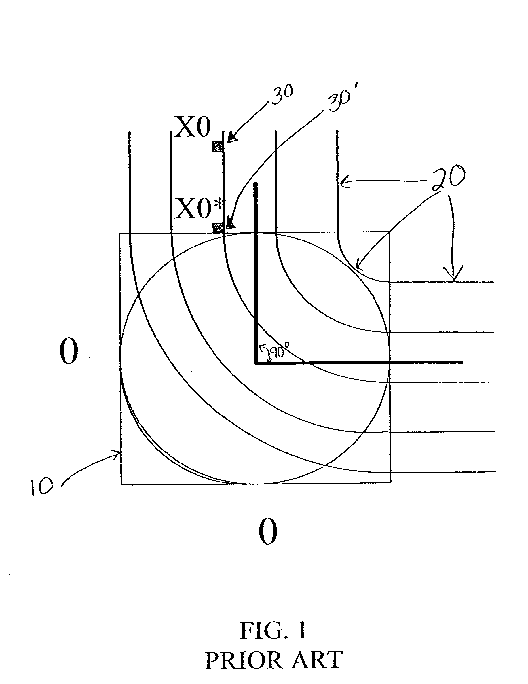
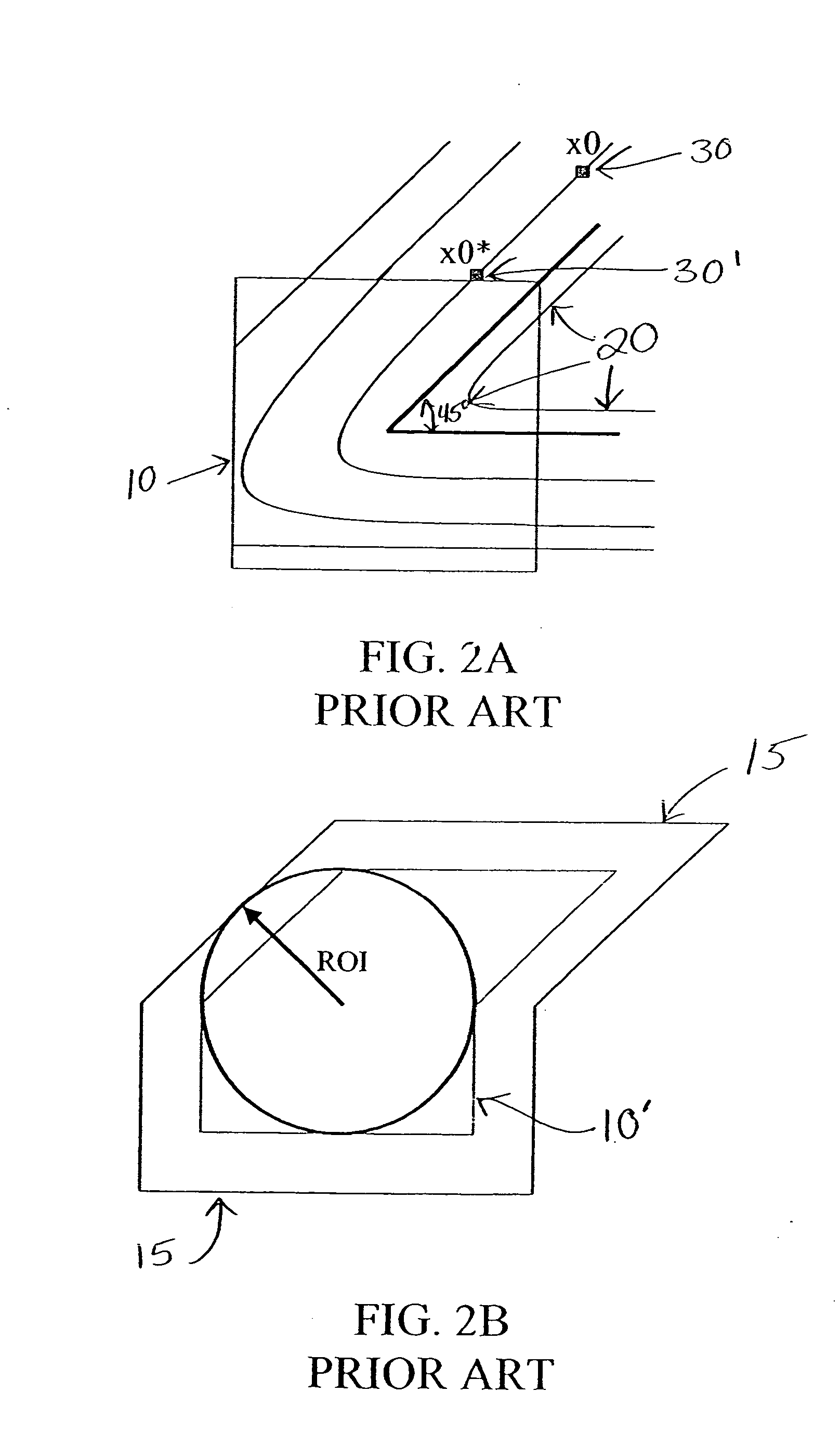
[0050] The present invention is directed to model-based optical proximity correction that initially locates a finite geometrical shape within a matrix having a region of interest (ROI) of a model-based simulation. The foregoing model-based optical proximity correction (OPC) is for use in optical lithography to ultimately correct for any distortions on a photomask having desired circuit patterns, for the accurate projection thereof onto photoresist-coated wafers.

[0051] It should be understood that the invention is suitable for use with any finite geometrical shape. In the preferred embodiment, the finite geometrical shape is a polygon. A polygon in a design is typically doffed by a set of vertex (vertices) and the corresponding sequence, for example by convention the left hand side of the f...


PUM


Abstract

Methods, and a program storage device for executing such methods, for performing model-based optical proximity correction by providing a mask matrix having a region of interest (ROI) and locating a plurality of points of interest within the mask matrix. A first polygon having a number of vertices representative of the located points of interest is computed, followed by determining a spatial relation between its vertices and the ROI. The vertices of the first polygon are then pinned to boundaries of and within the ROI such that a second polygon is formed on the ROI. The process is repeated for all vertices of the first polygon such that the second polygon is collapsed onto the ROI. This collapsed second polygon is then used to correct for optical proximity.

Description

CROSS-REFERENCE TO RELATED APPLICATIONS [0001] The present application is related to commonly assigned U.S. patent application Ser. No. ______ (Attorney Docket No. FIS920030107, titled “EXTENDING THE RANGE OF LITHOGRAPHIC SIMULATION INTEGRALS”), U.S. patent application Ser. No. ______ (Attorney Docket No. FIS920030108, titled “INCORPORATION OF A PHASE MAP INTO FAST MODEL-BASED OPTICAL PROXIMITY CORRECTION SIMULATION KERNELS TO ACCOUNT FOR NEAR AND MID-RANGE FLARE ”), U.S. patent application Ser. No. ______, (Attorney Docket No. FIS9200301 10, titled “RENESTING INTERACTION MAP INTO DESIGN FOR EFFICIENT LONG RANGE CALCULATIONS”), and U.S. patent application Ser. No. ______ (Attorney Docket No. FIS920030262, titled “SIMULTANEOUS COMPUTATION OF MULTIPLE POINTS ON ONE OR MULTIPLE CUT LINES”), filed on even date herewith, which are hereby incorporated by reference herein in their entirety.BACKGROUND OF THE INVENTION [0002] 1. Field of the Invention [0003] This invention relates generally ...

Claims


Application Information

Patent Timeline
IPC IPC(8): G03F1/08G03F1/14G03F7/20G06F17/10G06F17/50H01L21/00H01L21/027
CPCG03F1/36G03F1/144
Inventor GALLATIN, GREGG M.GOFMAN, EMANUELLAI, KAFAILAVIN, MARK A.MUKHERJEE, MAHARAJRAMM, DOVROSENBLUTH, ALAN E.SHLAFMAN, SHLOMO
Owner GLOBALFOUNDRIES INC
Why Eureka
Try Eureka