

Performance in model-based opc engine utilizing efficient polygon pinning method
a polygon pinning and model-based technology, applied in the field of optical lithography, can solve the problems of requiring a significant amount of memory, and a critical part of the model, and achieves the effect of reducing the number of data structures and numerical overhead, reducing computational time, and facilitating and cost-effective convoluted polygons
- Summary
- Abstract
- Description
- Claims
- Application Information
AI Technical Summary
Benefits of technology
Problems solved by technology
Method used
Image

Examples
Embodiment Construction
)
[0049] In describing the preferred embodiment of the present invention, reference will be made herein to FIGS. 1-5 of the drawings in which like numerals refer to like features of the invention.
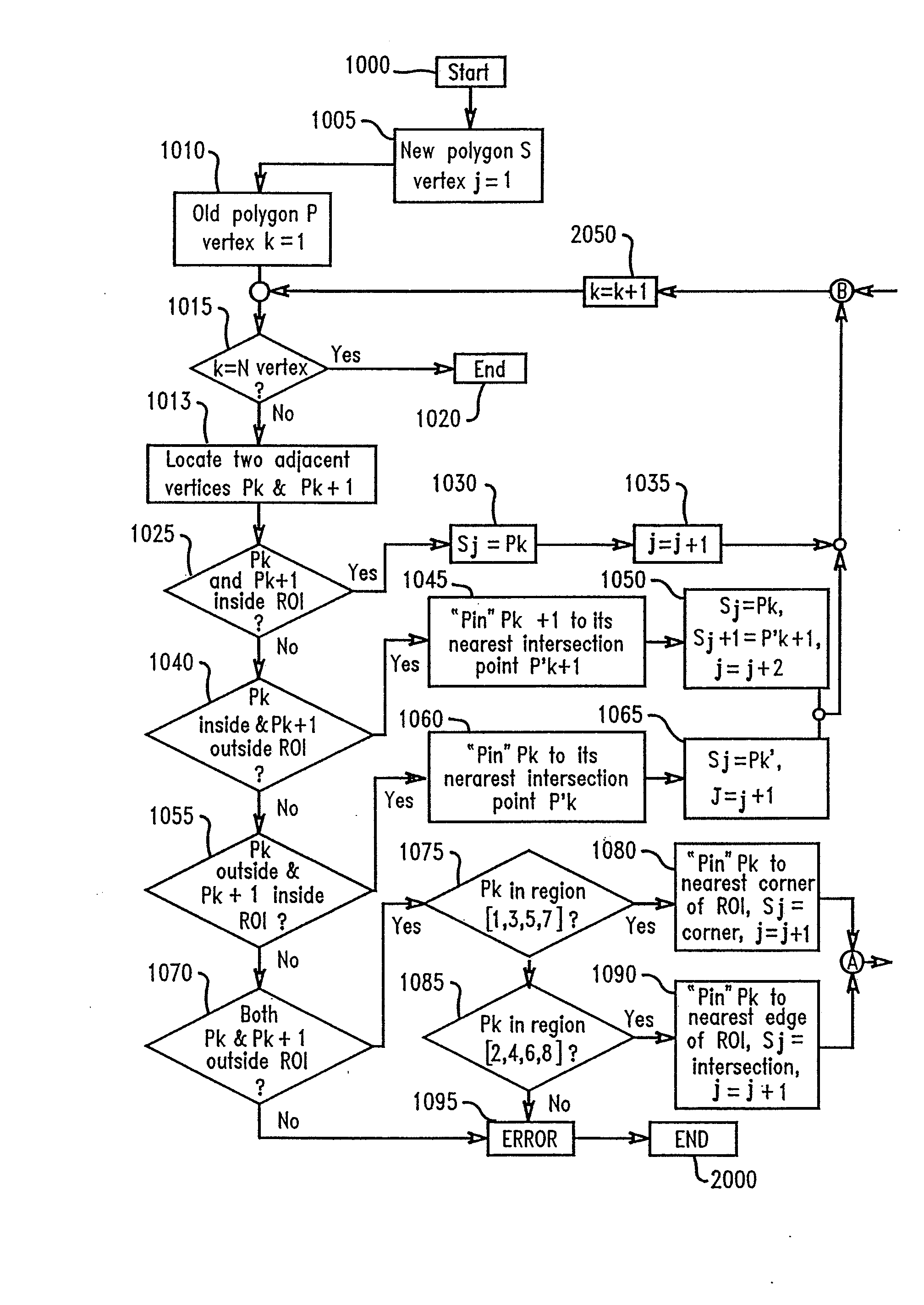
[0050] The present invention is directed to model-based optical proximity correction that initially locates a finite geometrical shape within a matrix having a region of interest (ROI) of a model-based simulation. The foregoing model-based optical proximity correction (OPC) is for use in optical lithography to ultimately correct for any distortions on a photomask having desired circuit patterns, for the accurate projection thereof onto photoresist-coated wafers.
[0051] It should be understood that the invention is suitable for use with any finite geometrical shape. In the preferred embodiment, the finite geometrical shape is a polygon. A polygon in a design is typically defined by a set of vertex (vertices) and the corresponding sequence, for example by convention the left hand side of the ...
PUM
| Property | Measurement | Unit |
|---|---|---|
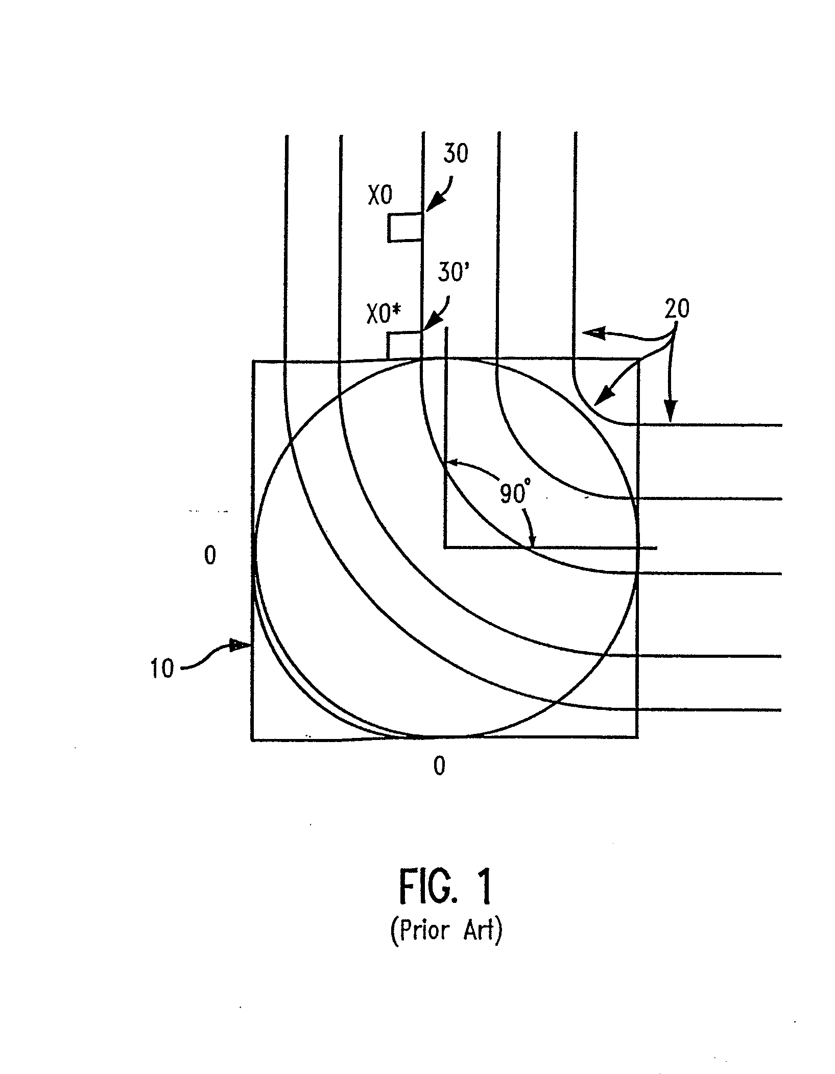
| 90 degree angles | aaaaa | aaaaa |
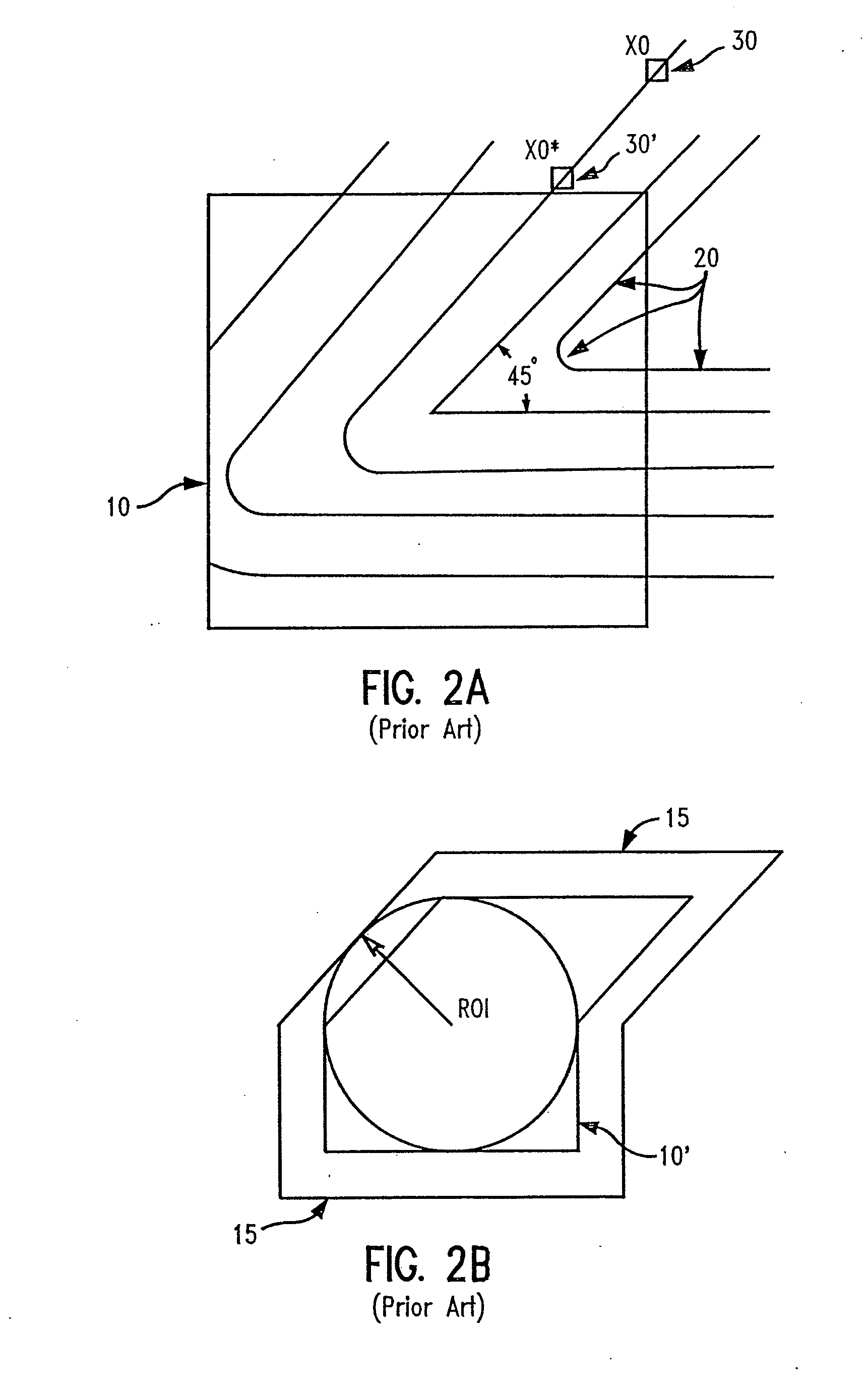
| 45 degree angles | aaaaa | aaaaa |
| optical proximity | aaaaa | aaaaa |
Abstract
Description
Claims
Application Information