

Supercharger
a supercharger and centrifugal technology, applied in the direction of electric generator control, piston pump, fluid coupling, etc., can solve the problems of difficult manufacturing of the very precise bores of the case components, the difficulty of machining, measuring and matching procedures, and the difficulty of manufacturing the assembly of the case components. to achieve the effect of convenient manufacturing and servi
- Summary
- Abstract
- Description
- Claims
- Application Information
AI Technical Summary
Benefits of technology
Problems solved by technology
Method used
Image

Examples
Embodiment Construction
[0026] In the following paragraphs, the present invention will be described in detail by way of example with reference to the attached drawings. Throughout this description, the preferred embodiment and examples shown should be considered as exemplars, rather than as limitations on the present invention. As used herein, the “present invention” refers to any one of the embodiments of the invention described herein, and any equivalents. Furthermore, reference to various feature(s) of the “present invention” throughout this document does not mean that all claimed embodiments or methods must include the referenced feature(s).
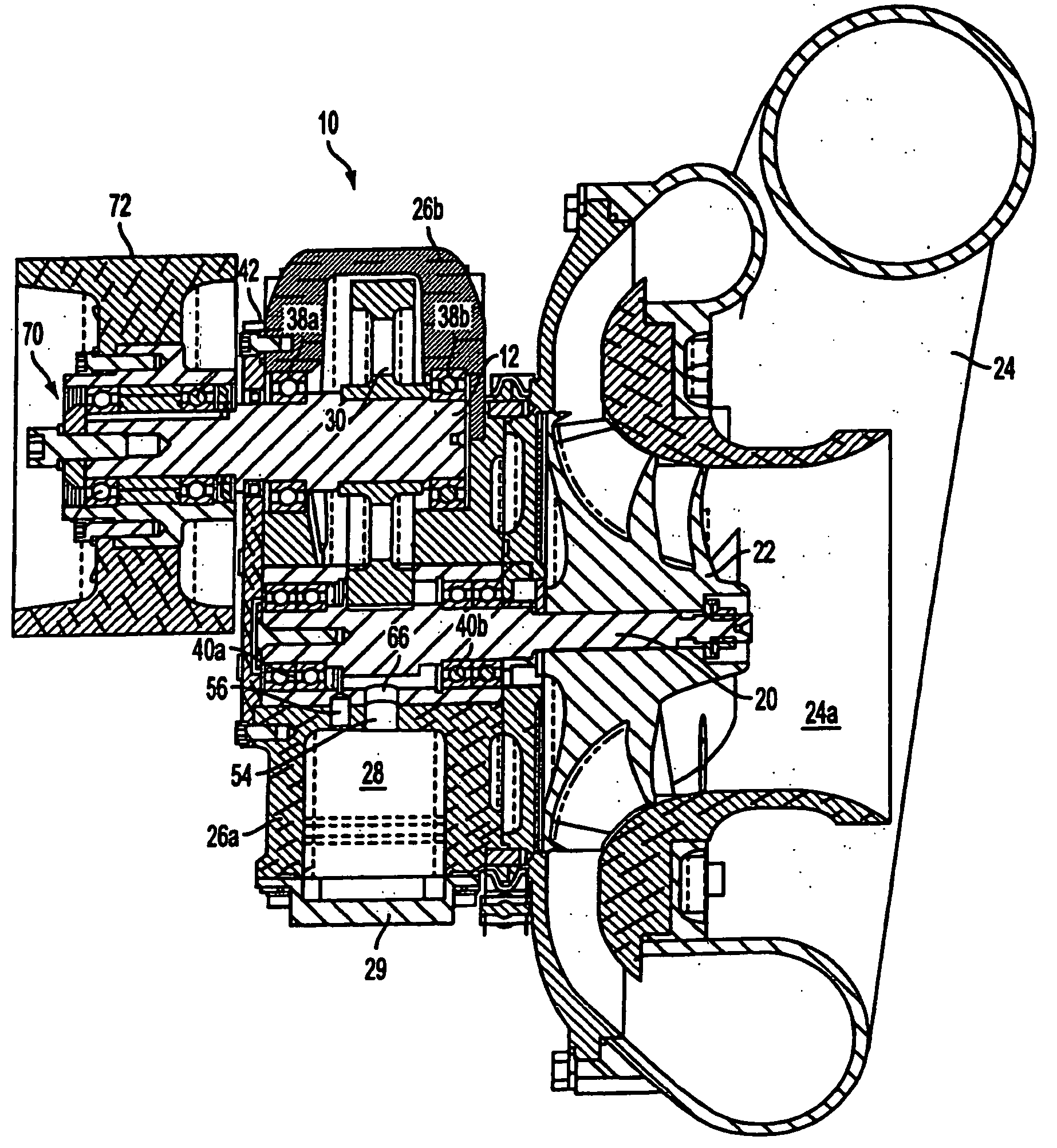
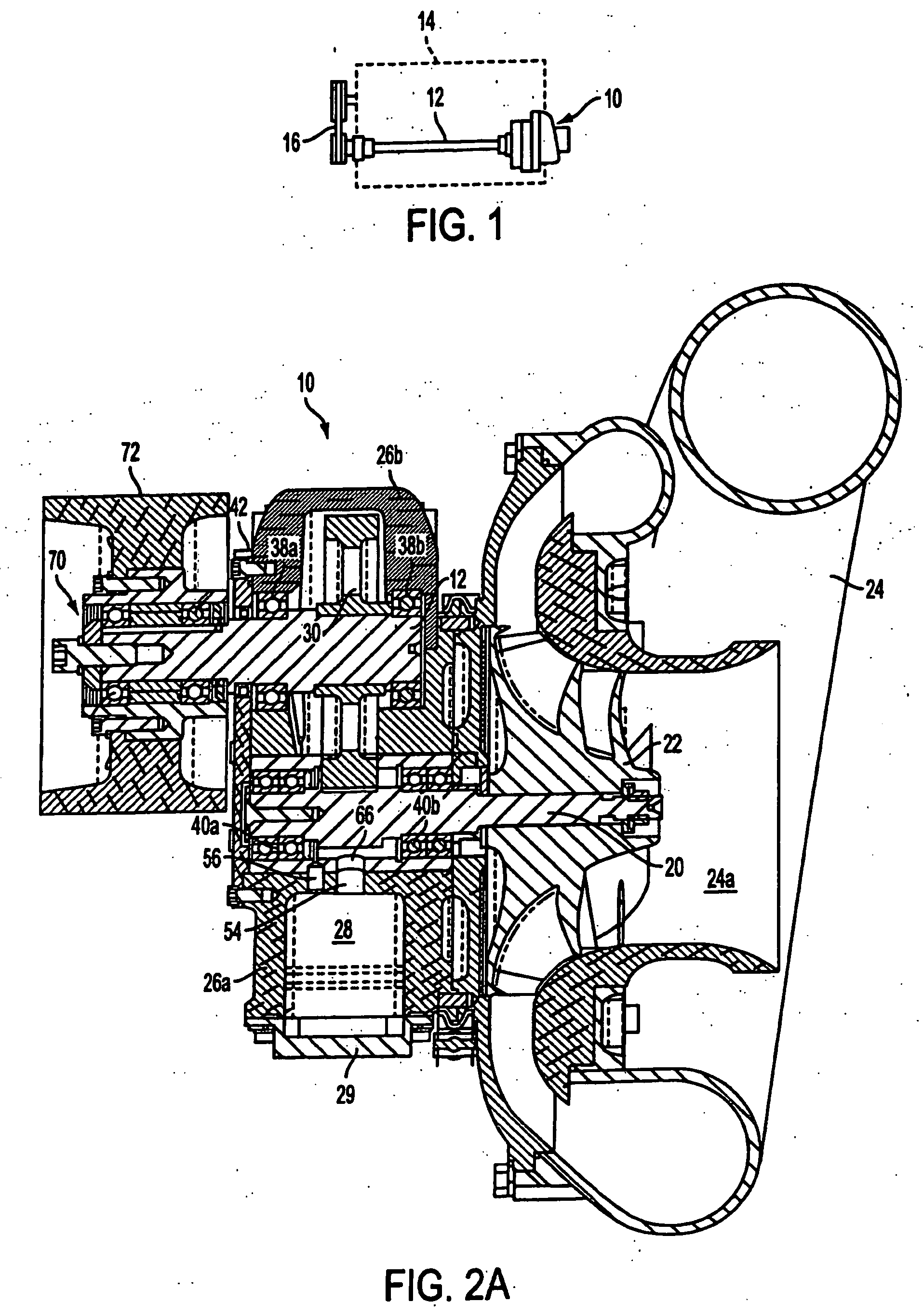
[0027] Referring to FIG. 1, a supercharger 10 constructed according to the present invention includes a driveshaft 12 for receiving rotational force from an engine 14 via a pulley and belt assembly 16. More particularly, one end of the driveshaft 12 is attached to supercharger 10 and the opposite end is attached to the pulley and belt assembly 16. In the illustrate...
PUM
 Abstract
Description
Claims
Application Information