
Fusion welding method and welded article

a technology of fusion welding and welded parts, which is applied in the direction of non-electric welding apparatus, storage discharge welding, machines/engines, etc., can solve the problems of general type of operating damage, operating damage, and damage to the radially outer blade end or tip portion of the blad

Inactive Publication Date: 2005-05-05
GENERAL ELECTRIC CO
View PDF10 Cites 12 Cited by
  • Summary
  • Abstract
  • Description
  • Claims
  • Application Information

AI Technical Summary

Benefits of technology

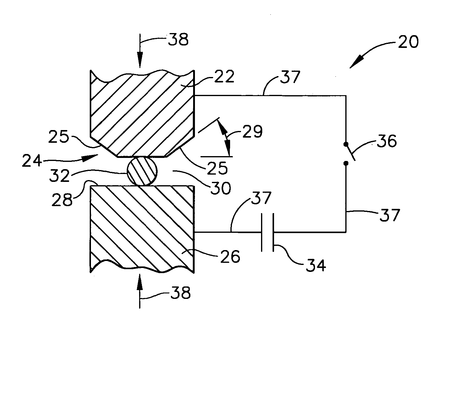
[0009] The present invention relates to fusion welding a first member having a first interface surface with a second member having a second interface surface. The first and second interface surfaces are disposed in contact and fusion welded together. In one form of the present invention, the first member is made of a first metal substantially free of at least one identified element that can form a substantially continuous brittle intermetallic compound layer at such first surface. The second member is made of a second metal that includes the at least one identified element that can form such continuous layer. In one method form, energy is generated at the interface surfaces in a combination of an amount and for a time sufficient to heat the first and second interface surfaces to a fusion welding temperature. However, such heating is for a first time that is less than a second time which enables formation at the fusion welding temperature of the substantially continuous layer of the brittle intermetallic compound at the interface surfaces.

Problems solved by technology

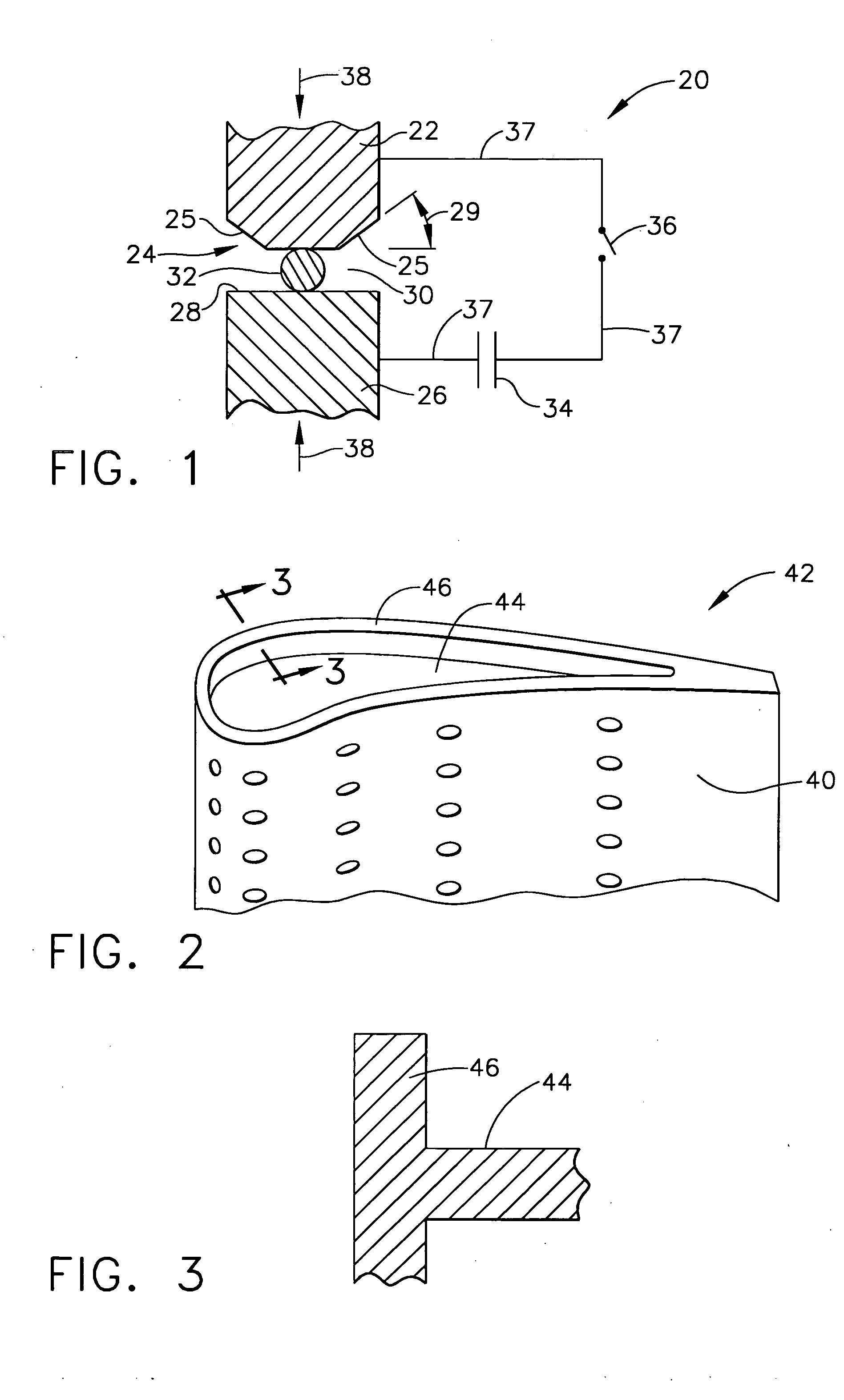
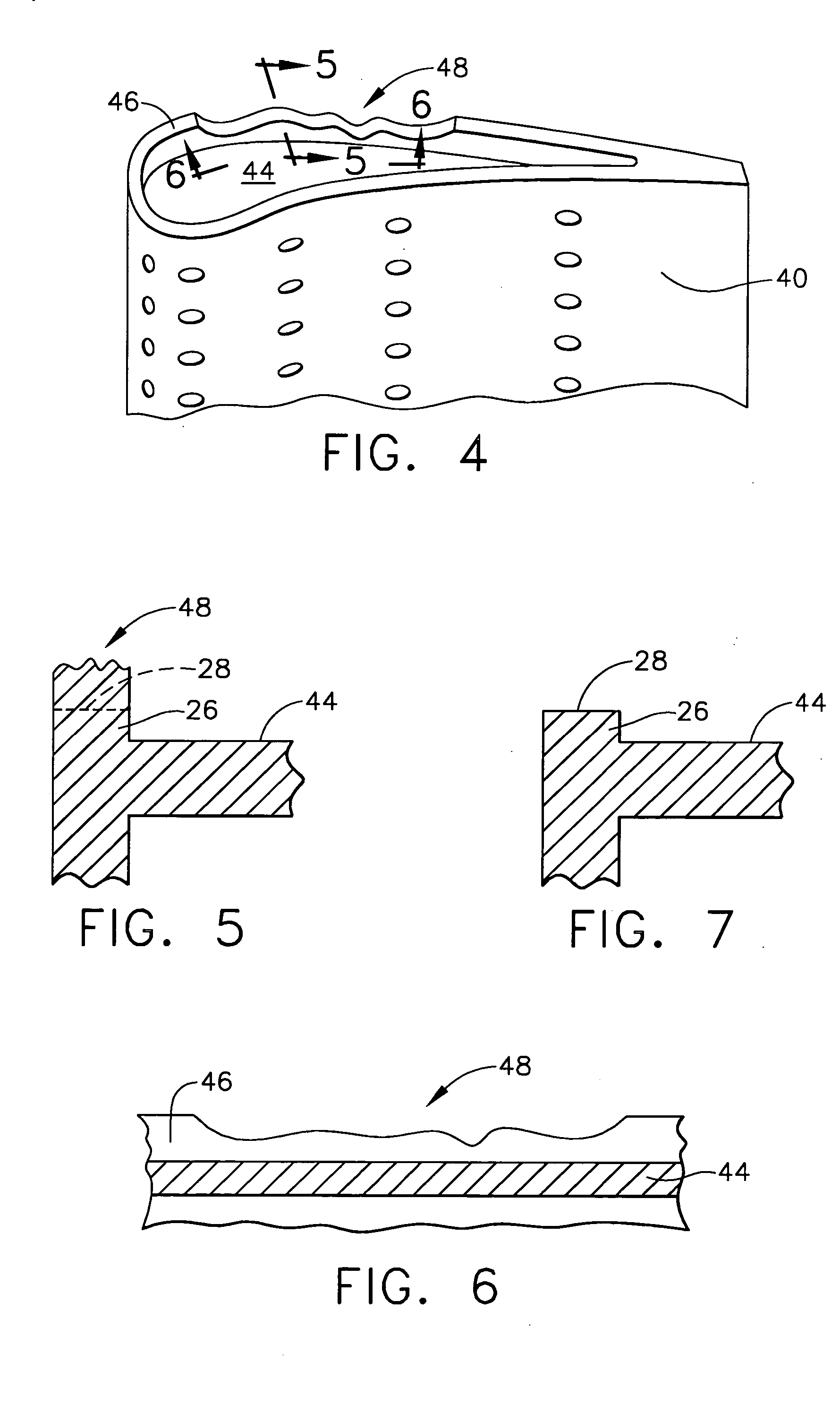
In one example, it was observed that the radially outer blade end or tip portion had been damaged apparently by hot gasses flowing over or across the blade tip and / or interference between the rotating blade tip and surrounding stationary structure.
This general type of operating damage has been observed for many years in the gas turbine engine art and a variety of methods and turbine blade tip configurations have been reported.
Another example of operating damage is article surface or coating damage or wear observed on discrete outer airfoil surfaces or areas along which higher temperature engine products of combustion flow.
Such intermixing has been observed to result in creation of a broader liquidussolidus band that upon cooling can generate stresses that can, under some circumstances, lead to cracking.
However, formation of a substantially continuous layer or film of a low ductility intermetallic at a weld between joined surfaces of certain dissimilar metals and / or alloys has been observed to result in weld cracking, either upon cooling after welding or after subsequent heating of the weld.
% Pt at a temperature up to about 1600° C. Accordingly, fusion welding of such combinations for a time in which Pt and Al can produce a substantially continuous layer of a brittle intermetallic compound in the weld region can result in a weld failure.
Cracks in the weld or its heat affected zone can form during or after welding, or as a result of heat treatment during subsequent manufacturing operations, or heating and cooling during service operation.
Therefore, current, typical fusion-type welding methods were found to be undesirable for welding a Ni-base superalloy, for example the above identified Rene′ N5 alloy including Al, to a high temperature noble metal or metal alloy not including Al, for example an alloy including nominally, in weight %, about 25 Pd, 34.5 Pt, 0.5 Zr and about 40 Rh.

Method used


Image

  • Fusion welding method and welded article
  • Fusion welding method and welded article
  • Fusion welding method and welded article

Examples


Embodiment Construction

[0026] Currently, weld repair of service damaged turbine blades made of high temperature superalloys such as Ni-base superalloys does not use high temperature metals or alloys based on the noble metals, for example Ru, Rh, Pd, and Pt. It has been observed that the combination of temperature and time at temperature of typical commercial fusion welding in the presence of at least one identified element in the superalloy, for example Al, has resulted in formation in the weld of an effectively substantially continuous thin layer of at least one brittle intermetallic compound that resulted in cracking of the weld and / or the weld heat affected zone adjacent the weld. However, such noble metals and their alloys offer great potential for extending the operating capability of turbine blades, particularly high pressure turbine blades, both as originally manufactured as well as in the repaired form. Forms of the present invention limit the time of interaction during interface fusion between co...


PUM

PropertyMeasurementUnit
timeaaaaaaaaaa
temperatureaaaaaaaaaa
angleaaaaaaaaaa

Abstract

A fusion welding method is provided for fusion welding at juxtaposed interface surfaces a first member, for example made of a first metal based on at least one of Ru, Rh, Pd, and Pt, with a second member made of a second metal, for example a high temperature alloy based on at least one of Fe, Co, and Ni, including at least one identified element, for example Al, that can form a continuous layer of a brittle intermetallic compound with the first metal that is free of such element. With the interface surfaces disposed in contact, energy is generated at the interface surfaces in a combination of an amount and for a first time selected to be sufficient to heat the interface surfaces to a fusion welding temperature. However, the first time is less than a second time that enables formation at the fusion welding temperature of the continuous layer of the brittle intermetallic compound at the interface surfaces. A welded article is provided with a fusion weld free of such continuous layer of the brittle intermetallic compound.

Description

BACKGROUND OF THE INVENTION [0001] This invention relates to fusion-type welding of members made of different, dissimilar alloys and, more particularly, to such welding of alloys at least one of which includes an element that can form a substantially continuous layer of a brittle, low ductility intermetallic compound in a resulting weld. [0002] Power generating apparatus, for example gas turbine engines, includes, in the hotter operating sections such as the turbine section, components made of high temperature alloys based on at least one of the elements Fe, Co, and Ni. Sometimes called superalloys, a typical example of frequently used superalloys is the Ni-based superalloy that can included alloying elements for a variety of purposes including precipitation strengthening, solid solution strengthening, and / or high temperature environmental resistance. An example of one of such elements of particular interest to the present invention is Al included in Ni base superalloys at least for...

Claims


Application Information

Patent Timeline
Patent Type & Authority Applications(United States)
IPC IPC(8): F01D25/00B23K11/11B23K11/20B23K11/26B23K20/00B23K103/18F02C7/00
CPCB23K11/115B23K2201/001Y10S428/934Y10S428/926Y10T428/12847Y10T428/12854Y10T428/12986Y10T428/12806Y10T29/49318Y10T428/12931Y10T428/12861Y10T428/12875B23K2101/001
Inventor TREWILER, GARY EDWARD
Owner GENERAL ELECTRIC CO
Learn More