Thin-film acoustically-coupled transformer

a technology of acoustically coupled transformers and thin films, applied in piezoelectric/electrostrictive/magnetostrictive devices, piezoelectric/electrostriction/magnetostriction machines, semiconductor devices, etc., can solve the problems of coil-based transformers becoming impractical, not all transformers have all of these properties, etc., to achieve less importance, and high common-mode rejection ratio

Active Publication Date: 2005-05-05
AVAGO TECH INT SALES PTE LTD
View PDF15 Cites 32 Cited by
  • Summary
  • Abstract
  • Description
  • Claims
  • Application Information

AI Technical Summary

Benefits of technology

[0012] Some embodiments of the acoustically-coupled transformer in accordance with the invention are inherently electrically balanced and have a higher common-mode rejection ratio than the above-described embodiment having the single SBAR. In such embodiments, the first electrical circuit electrically connects one of the FBARs of the first SBAR either in anti-parallel or in series with one of the FBARs of the second SBAR, and the second electrical circuit electrically connects the other of the FBARs of the first SBAR either in anti-parallel or in series with the other of the FBARs of the second SBAR. An embodiment of the acoustically-coupled transformer in which the first electrical circuit connects the respective FBARs in anti-parallel and the second electrical circuit connects the respective FBARs in anti-parallel has a 1:1 impedance transformation ratio between the first electrical circuit and the second electrical circuit and vice versa. An embodiment in which the first electrical circuit connects the respective FBARs in series and the second electrical circuit connects the respective FBARs in series also has a 1:1 impedance transformation ratio between the first electrical circuit and the second electrical circuit and vice versa. However, the impedances are higher than the embodiment in which the FBARs are connected in anti-parallel. An embodiment of the acoustically-coupled transf...

Problems solved by technology

However, not all transformers have all of these properties.
For example, an auto-transformer does not provide electrical isolation.
At UHF and microwave frequencies, coil-based transformers become impractical due to such factors as losses in the core, losses in the windings, capacitance between the windings, and a difficulty to make them small enough to prevent wavelength-related problems.
Transformers also exist that are based on micro-machined coupled coils sets and are small enough that wavelength effects are unimportant.
However such transformers have issues with high insertion loss.
All the transformers just described for use at UHF and microwave frequencies have dimensions t...

Method used


Image

  • Thin-film acoustically-coupled transformer
  • Thin-film acoustically-coupled transformer
  • Thin-film acoustically-coupled transformer

Examples


first embodiment

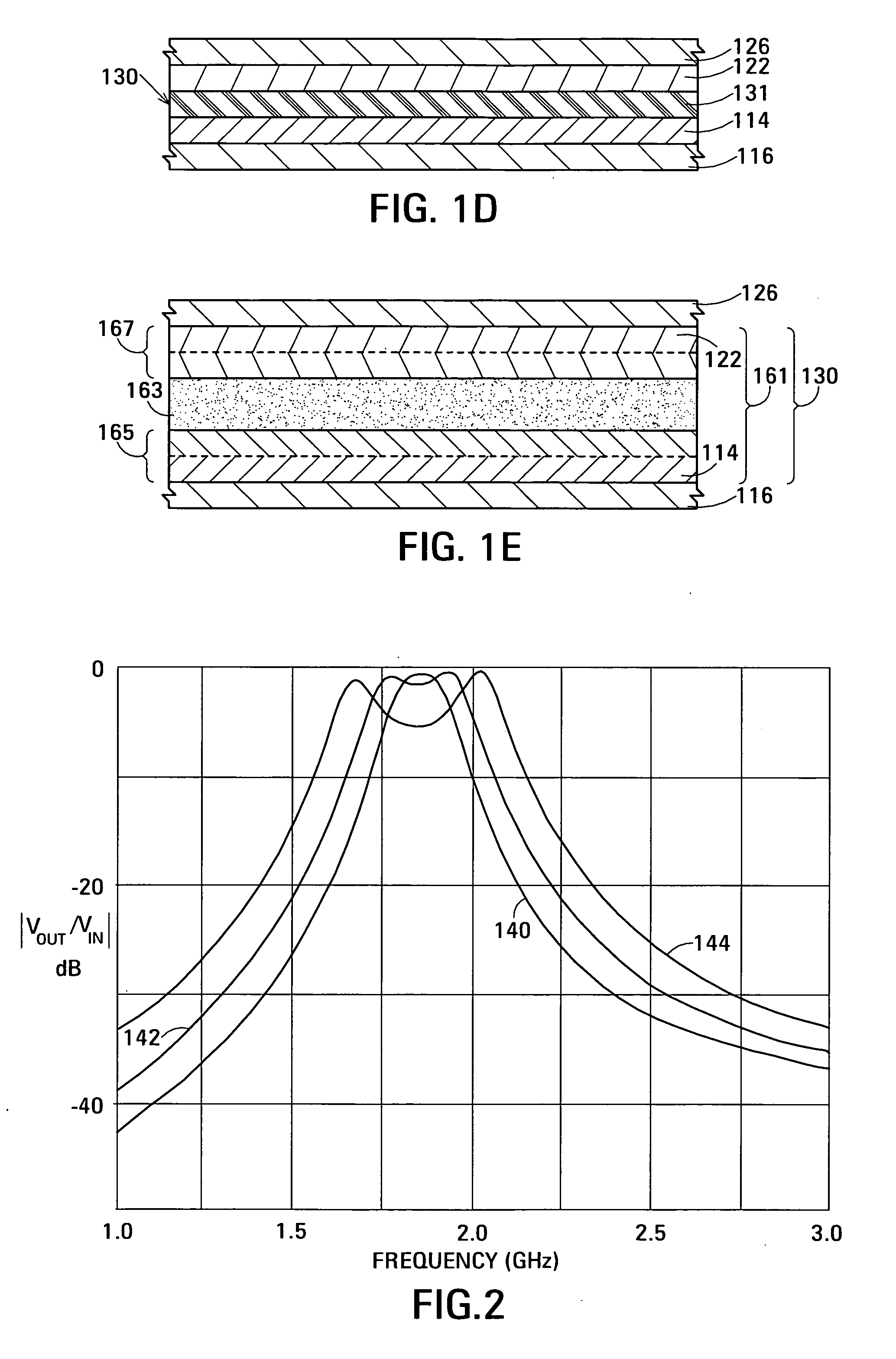
[0033]FIG. 2 is a graph showing how the calculated frequency response of thin-film acoustically-coupled transformer 100 depends on the acoustic impedance of the acoustic decoupling material of layer 131 that constitutes acoustic decoupler 130. The embodiment illustrated has a center frequency of about 1,900 MHz. Calculated frequency responses for embodiments in which the acoustic decoupling material of the acoustic decoupler has acoustic impedances of about 4 Mrayl (polyimide-curve 140), 8 Mrayl (curve 142) and 16 Mrayl (curve 144) are shown. It can be seen that the bandwidth of transformer 100 increases with increasing acoustic impedance of the acoustic decoupling material. In the embodiment in which the acoustic impedance is 16 Mrayl, the resonances of the FBARs are over coupled, which causes the characteristic double peak in the pass band response.

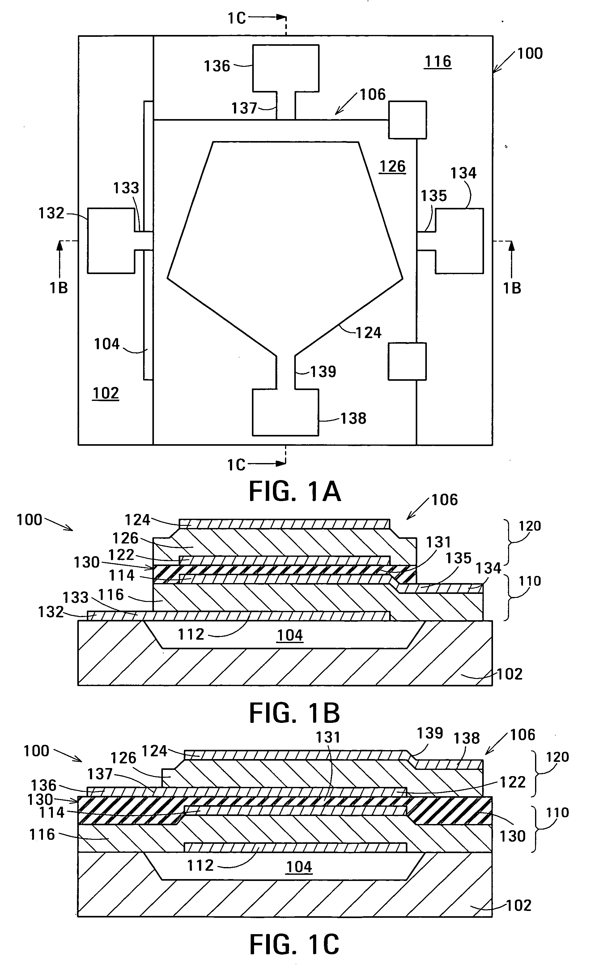
[0034] The embodiment of acoustic decoupler 130 shown in FIGS. 1B, 1C and 1D is composed of layer 131 of acoustic decoupling material ...

second embodiment

[0040]FIG. 1E is an enlarged view of part of thin-film acoustically-coupled transformer 100 showing acoustic decoupler 130 that incorporates a Bragg structure 161. Bragg structure 161 is composed of a low acoustic impedance Bragg element 163 sandwiched between high acoustic impedance Bragg elements 165 and 167. Low acoustic impedance Bragg element 163 is a layer of a low acoustic impedance material whereas high acoustic impedance Bragg elements 165 and 167 are each a layer of high acoustic impedance material. The acoustic impedances of the Bragg elements are characterized as “low” and “high” with respect to one another and additionally with respect to the acoustic impedance of the piezoelectric material of layers 116 and 126. At least one of the Bragg elements additionally has a high electrical resistivity and a low dielectric permittivity to provide electrical isolation between input and output of transformer 100.

[0041] Each of the layers constituting Bragg elements 161, 163 and 16...


PUM

PropertyMeasurementUnit
Massaaaaaaaaaa
Thicknessaaaaaaaaaa
Structureaaaaaaaaaa

Abstract

One embodiment of the acoustically-coupled transformer includes a stacked bulk acoustic resonator (SBAR) having a stacked pair of film bulk acoustic resonators (FBARs) with an acoustic decoupler between them. Each FBAR has opposed planar electrodes with piezoelectric material between them. The transformer additionally has first terminals electrically connected to the electrodes of one FBAR and second terminals electrically connected to the electrodes of the other FBAR. Another embodiment includes first and second stacked bulk acoustic resonators (SBARs), each as described above, a first electrical circuit connecting one FBARs of the first SBAR to one FBAR of the second SBAR, and a second electrical circuit connecting the other FBAR of the first SBAR to the other FBAR of the second SBAR. The transformer provides impedance transformation, can linking single-ended circuitry with balanced circuitry or vice versa and electrically isolates primary and secondary. Some embodiments are additionally electrically balanced.

Description

RELATED APPLICATION [0001] This application is related to U.S. patent application Ser. No. ______ of John D. Larson III entitled Stacked Bulk Acoustic Resonator Band-Pass Filter with Controllable Pass Bandwidth (Agilent Docket No. 10030669), filed on the filing date of this application and incorporated into this application by reference.BACKGROUND OF THE INVENTION [0002] Transformers are used in many types of electronic device to perform such functions as transforming impedances, linking single-ended circuitry with balanced circuitry or vice versa and providing electrical isolation. However, not all transformers have all of these properties. For example, an auto-transformer does not provide electrical isolation. [0003] Transformers operating at audio and radio frequencies up to VHF are commonly built as coupled primary and secondary windings around a high permeability core. The core contains the magnetic flux and increases the coupling between the windings. A transformer operable in...

Claims


Application Information

Patent Timeline
IPC IPC(8): H03H9/13H03H9/17H03H9/60
CPCH03H9/132H03H9/584Y10T29/42H03H9/605H03H9/587H01L2224/48091H01L2224/49175H01L2924/00014H03H9/60H03H9/0095
Inventor LARSON, JOHN D. IIIRUBY, RICHARD C.
Owner AVAGO TECH INT SALES PTE LTD
Why Eureka
Try Eureka