Red phosphor and method of preparing the same, and red light emitting diode, white light emitting diode, and active dynamic liquid crystal device using the red phosphor

Active Publication Date: 2005-05-05
SAMSUNG ELECTRONICS CO LTD +1
View PDF2 Cites 19 Cited by
  • Summary
  • Abstract
  • Description
  • Claims
  • Application Information

AI Technical Summary

Benefits of technology

[0011] The present invention provides a red phosphor that exhibits high emis

Problems solved by technology

In this case, however, the white LEDs have a high manufacturing cost, and are bulky due to complex driving circuits.
However, this white light has only a portion of the visible range spectrum, which results in a small color rendering index and poor color rendition.
In addition, since the blue LED, which is used as a light source in this case, has a wavelength of 450 nm, chip efficiency i

Method used


Image

  • Red phosphor and method of preparing the same, and red light emitting diode, white light emitting diode, and active dynamic liquid crystal device using the red phosphor
  • Red phosphor and method of preparing the same, and red light emitting diode, white light emitting diode, and active dynamic liquid crystal device using the red phosphor
  • Red phosphor and method of preparing the same, and red light emitting diode, white light emitting diode, and active dynamic liquid crystal device using the red phosphor

Examples


example 1

PRELIMINARY EXAMPLE 1

[0044] Manufacture of Li(2-z)(MoO4)2:Euz Phosphor

[0045] Li2CO3, Eu2O3, and MoO3 were prepared as precursors of lithium, Eu, and Mo. Li2CO3, Eu2O3, and MoO3 were mixed in a proper stoichiometric ratio with an acetone solvent in a mortar. The resultant slurry was placed in an alumina reactor to be subjected to calcination in the presence of air at 600˜1000° C. for 3 hours. The calcination result was washed with distilled water. The amount of the active material Eu, which is denoted by the z value, varies in the range of 0.01-1.3. Optimum emission characteristics occurred when the value of z was 0.8. When the value of z is greater than 0.8, a concentration calcination phenomenon occurs, decreasing emission. When the concentraion of Eu is smaller than 0.8, the concentration of the active agent is too low, decreasing emission intensity. Optimum emission characteristics appeared when the calcination temperature was 900° C. When the calcination temperature was lower t...

examples 1-5

[0046] Manufacture of the Li(2-z)(MoO4)2:Euz,Smq Phosphor

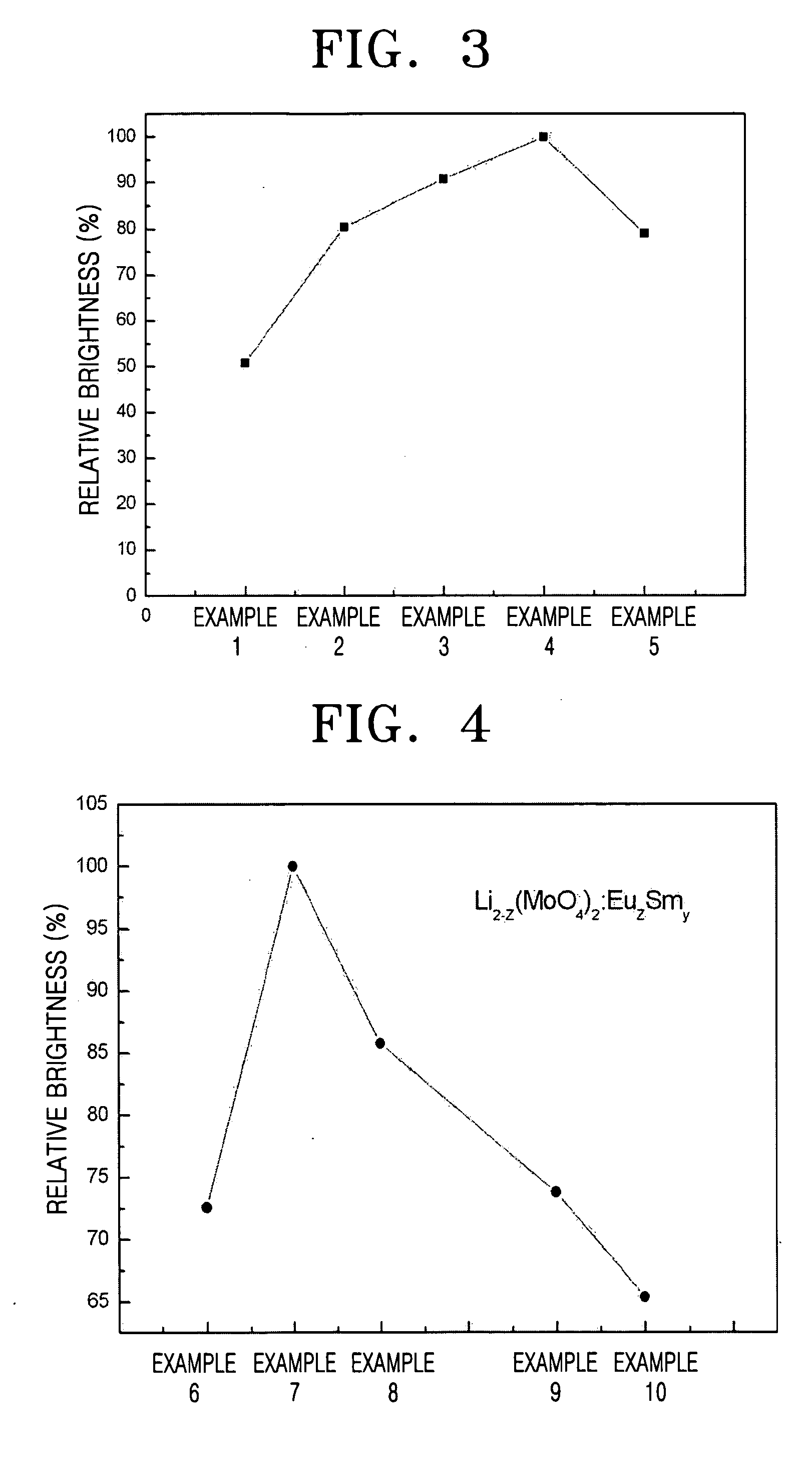
[0047] In this process, red phosphors were manufactured in the same manner as in Preliminary Example 1, except that the amount of Eu (z) was fixed to 0.8 and the amount of Sm (q) varied as shown in Table 1. Relative emission intensity of the red phosphors was measured using an excitation light source of 394 nm. The results are shown in FIG. 3.

TABLE 1Variation of amount of Sm in red phosphorAmount of Sm(q)Example 10.02Example 20.04Example 30.06Example 40.08Example 50.10

[0048] As is apparent in FIG. 3, the relative emission intensity was greatest in Example 4 where the amount of Sm (q) was 0.08.

examples 6-10

[0049] Manufacture of the Li(2-z)(MoO4)2:Euz,Smq Phosphor

[0050] Red phosphors were manufactured in the same manner as in Example 1, except that the amount of Sm (q) was fixed to 0.08 and the amount of Eu (z) varied as shown in Table 2. Relative emission intensity of the red phosphors was illustrated in FIG. 4. As is apparent in FIG. 4, the relative emission intensity was greatest in Example 7:

TABLE 2Variation of amount of Eu in red phosphorAmount of Eu (z)Example 60.7Example 70.8Example 80.9Example 91.0Example 101.1


PUM


Abstract

Provided is a red phosphor represented by formula 1:
(Li(2-z)-xMx)(MoO4)y:Euz,Smq  (1)
where M is an element selected from K, Mg, Na, Ca, Sr, and Ba, 0≦x≦2, 0.5≦y≦5, 0.01≦z≦1.5, and 0.001≦q≦1.0. The red phosphor has emission characteristics such as high brightness when excited by, in particular, an excitation light source of around 405 nm. The red phosphor is 6 times brighter than conventional phosphors. Furthermore, the red phosphor can be used in a red light emitting diode (LED) that has a UV excitation light source, a white LED, and an active dynamic liquid crystal device (LCD). In addition, the white LED using the red phosphor has a color rendering index of 90 or greater and so has excellent color rendition.

Description

[0001] This application claims the priority of Korean Patent Application No. 2003-77185, filed on Nov. 1, 2003, in the Korean Intellectual Property Office, the disclosure of which is incorporated herein in its entirety by reference. BACKGROUND OF THE INVENTION [0002] 1. Field of the Invention [0003] The present invention relates to a red phosphor, and more particularly to a red phosphor with high emission efficiency, a method of preparing the red phosphor, and a red light emitting diode, a white light emitting diode, and an active dynamic liquid crystal device using the red phosphor. [0004] 2. Description of the Related Art [0005] White light emitting diodes (LEDs) have a longer lifetime than incandescent light bulbs (a popular type 60 W) can be manufactured in small sizes, and operated at a low voltage. Therefore, white LEDs are recognized as an alternative light source in areas such as domestic fluorescent lamps, liquid crystal device (LCD) backlights, and the like. [0006] White L...

Claims


Application Information

Patent Timeline
IPC IPC(8): C09K11/08C09K11/59G02F1/13357C09K11/68C09K11/73C09K11/77H01L33/50H01L33/54H01L33/56
CPCC09K11/7783Y02B20/181H01L2224/48091H01L2224/48247H01L2224/48257H01L2224/48465H01L2924/00014H01L2924/00H01L2924/181Y02B20/00H01L2924/00012G02F1/1335
Inventor KANG, YUN-CHANCHO, JAE-HEESONE, CHEOL-SOO
Owner SAMSUNG ELECTRONICS CO LTD
Why Eureka
Try Eureka