Method of monitoring quality of communication for each flow

a communication flow and quality technology, applied in the field of monitoring communication flows, can solve the problems of increasing intra-ip-network traffic, heavy processing load of meter readers, bottlenecks in core network performance, etc., and achieve the effect of improving reliability for users and low cos

Inactive Publication Date: 2005-05-05
HITACHI LTD
View PDF3 Cites 42 Cited by
  • Summary
  • Abstract
  • Description
  • Claims
  • Application Information

AI Technical Summary

Benefits of technology

[0016] Recently, assurance of communications performance and quality by Service Level Agreement (SLA) has been viewed as a business means for Internet Service Providers (ISPs) The SLA defines the availability of network resources (e.g. bandwidth), delay time, and fault information (maintenance time). In addition, minimum bandwidth within which reliable transmission is guaranteed and a packet loss rate can be defined in the SLA. If the ISP contravenes the SLA as contracted, the ISP must compensate for the user under contract with the ISP. Thus, it is important for the ISP to prove the fulfillment of the SLA to the user as well as administrate its network without contravening the SLA. If the ISP provides a traffic monitoring service that comprises monitoring communication service per communication flow for the user whom the ISP contracted for SLA and presenting the result data obtained by monitoring to the user, thereby proving the fulfillment of the SLA, its reliability for the user can be enhanced and this will be beneficial for the business.
[0017] An object of the present invention is to provide network monitoring method and hardware expandable with low cost and suitable for collecting traffic statistics data from the meters that observe calls (communication flows) and measure such data per call (communication flow), which is applicable to a large-scale IP network.

Problems solved by technology

With the increase of the number of packet switches as components of the IP network to which the conventional traffic monitoring and statistics collection technique described above is applied, that is, as the IP network expands, the following problems arise:
Consequently, a problem arises that the intra-IP-network traffic increases.
Because packets sent from the edge nodes placed on the edges of the IP network are concentrated in the core of the IP network, such traffic increase causes a bottleneck of core network performance.
(2) If the network manager and meter reader accommodate many packet switches to be managed, the processing load of the meter reader becomes heavy.
Another problem is that the performance of the network management system must be improved as the network expands.
Because each packet switch generally operates, based on different time information (clock), it is very difficult to analyze the collected statistics data in terms of time sequence and causation.
Consequently, a problem of time inconsistency of the statistics data collected from the packet switches arises.

Method used


Image

  • Method of monitoring quality of communication for each flow
  • Method of monitoring quality of communication for each flow
  • Method of monitoring quality of communication for each flow

Examples


Embodiment Construction

[0034] How the invention can be embodied will be explained below with reference to the drawings.

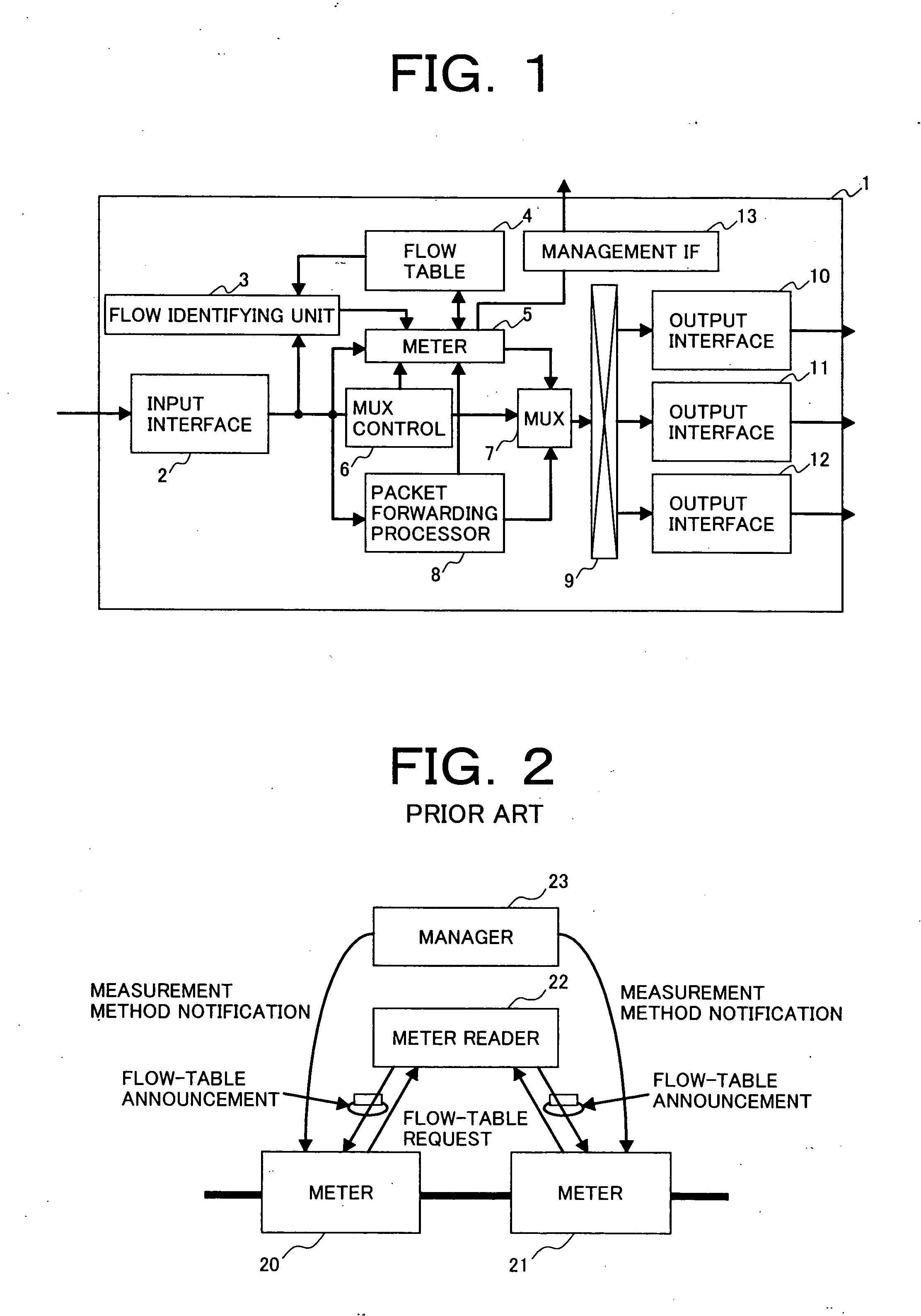
[0035]FIG. 1 is a block diagram showing the configuration of a packet switch that implements monitoring communication flows and collecting statistics data thereof, according to the method of the present invention. A packet switch 1 comprises an input interface (hereinafter referred to as an input IF) 2, a flow identifying unit 3, an packet forwarding processor 8, MUX control 6, a meter 5, a flow table 4, a management interface (hereinafter referred to as management IF) 13, multiplexer 7, a switch 9, and a plurality of output interfaces (hereinafter referred to as output IFs) 10, 11, and 12. Although practical packet switches generally perform two-way transmission operation with input and output IF pairs, the discussion herein focuses on only one-way packet forwarding for easy understanding of the method of the present invention.

[0036] How the packet switch 1 operates will be now explain...


PUM


Abstract

A packet switch identifies a communication flow carried across an IP network, observes the communication flow, and acquires statistics data thereof, such as the number of packets that passed through the switch, the number of discarded packets, time at which the packets arrived at the switch, and time at which the packets were sent out from the switch. The packet switch continues to acquire the statistics data on the communication flow while the communication flow continues. If the packet switch performs a relay function, it sends the locally obtained statistics data to the adjoining packet switch placed downstream. If the packet switch is a node placed on either end edge of the network, it gathers the statistics data obtained by and delivered from other switches in the network and sends the gathered statistics data to the network management system.

Description

BACKGROUND OF THE INVENTION [0001] 1. Field of the Invention [0002] The present invention relates to a method of monitoring communication flows carried across a network and hardware that implements monitoring, using such method. Particularly, the invention relates to such network monitoring method and hardware intended for efficiently collecting and analyzing the statistics data on packets per communication flow transmitted across a network that provides packet switching by using Internet Protocol (this network is hereinafter referred to as an IP network) in order to use such statistics data for charging and other administrative tasks. [0003] 2. Description of Related Art [0004] Existing IP networks are administrated, based on a policy called a best effort: i.e., a network provides the best transmission performance that it can accomplish by using the maximum available resources for communication (for example, transmission bandwidth and delay time) in the network. As the IP networks ...

Claims


Application Information

Patent Timeline
Patent Type & Authority Applications(United States)
IPC IPC(8): H04L1/20H04M3/36H04L12/24H04L12/26H04L12/70
CPCH04L1/0026H04L1/20H04L41/5003H04L41/5009H04L43/02H04L43/026H04L2012/5628H04L43/0829H04L43/0852H04L43/0876H04L43/0888H04L43/106H04L43/065
Inventor MIMURA, ITARUNAGASAKA, MITSURUENDO, NOBORU
Owner HITACHI LTD
Why Eureka
Try Eureka