

Channel communication apparatus and method in CDMA communication system
- Summary
- Abstract
- Description
- Claims
- Application Information
AI Technical Summary
Benefits of technology
Problems solved by technology
Method used
Image

Examples
Embodiment Construction
[0050] Preferred embodiments of the present invention will be described in detail referring to the attached drawings. Like reference numerals denote the same components and it is to be noted that a detailed description of a known function or structure of the present invention will be omitted if it is deemed to obscure the subject matter of the present invention.
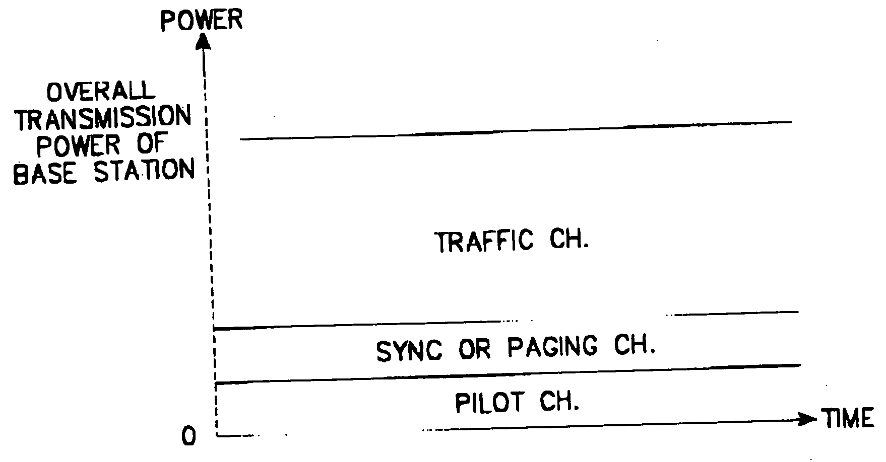
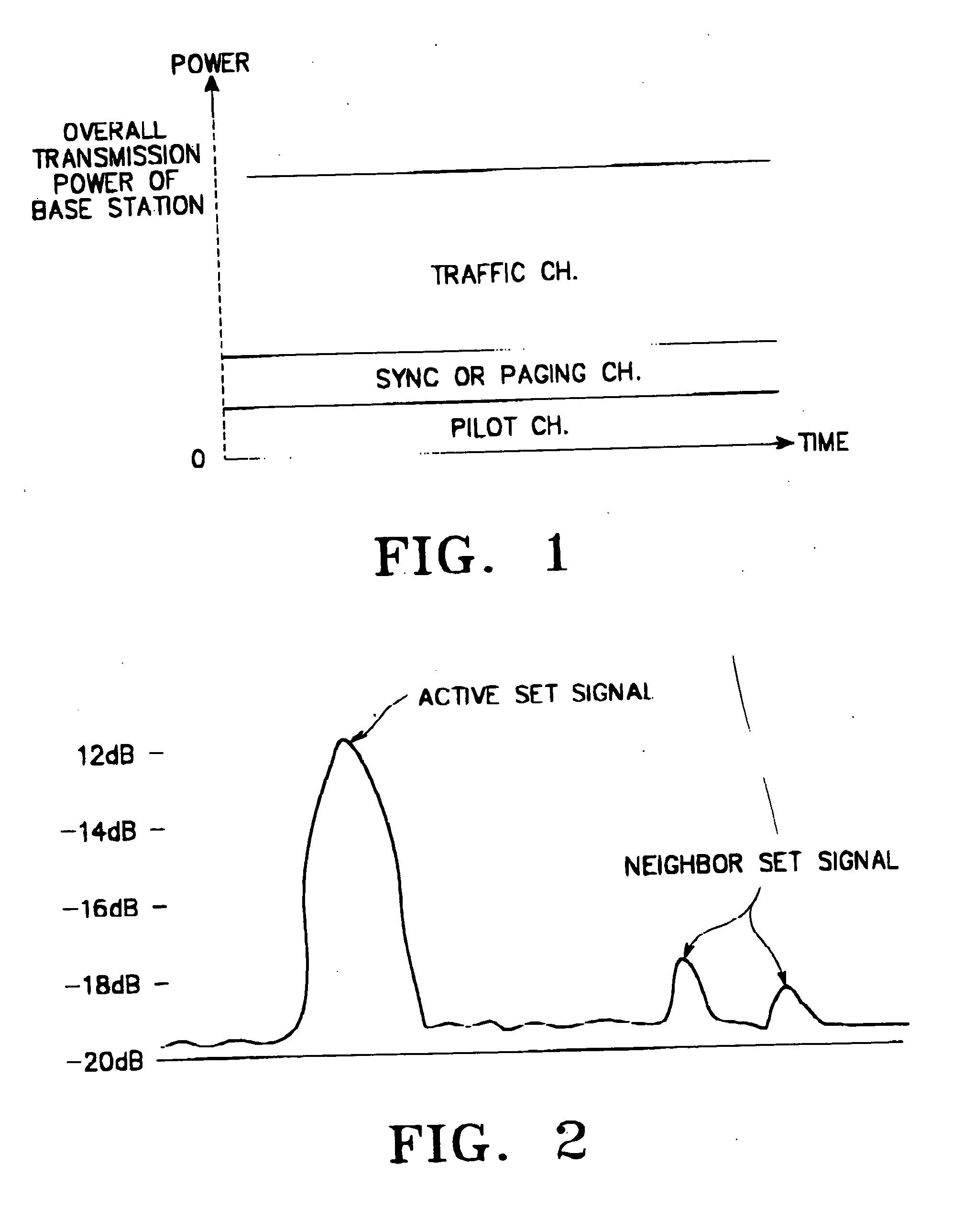
[0051] In accordance with an embodiment of the present invention, a base station sends a pilot signal on a forward pilot channel at an increased power level for a specified time period in order to allow efficient search in a terminal. The terminal despreads the received signal at the higher power level for a specified time period, detects signals from a plurality of base stations, and measures the signal level, delay, or delay relative to other paths of a multipath signal received from each base station.
[0052] It should be noted that the following description of the present invention refers to the other channels except for ...
PUM
 Abstract
Description
Claims
Application Information