Methods of performing medical procedures with catheter systems having movable member

a technology of movable members and catheters, applied in the field of catheters, can solve the problems of patient progressive loss of other conventional long-term vascular access possibilities, two catheterization techniques are significantly different in their complexity and degree of invasiveness

Inactive Publication Date: 2005-05-05
CATHLOGIC
View PDF65 Cites 39 Cited by
  • Summary
  • Abstract
  • Description
  • Claims
  • Application Information

AI Technical Summary

Benefits of technology

[0022] It is therefore an object of the present invention to provide a new and useful catheter system for use in a body of a patient.
[0023] It is also an object of the present invention to provide a new and useful long-term catheter system for use in a body of a patient.
[0024] It is another object of the present invention to provide ...

Problems solved by technology

On the other hand, when a procedure is performed to effect hemodialysis, a physician may place a catheter in the blood vessel for a relatively long period of time.
Firstly, a patient may have experienced progressive loss of other conventional long term vascular access possibilities such as surgically created arteriovenous fistulas.
These two catheterization techniques are significantly different with respect to their complexity and degree of invasiveness.
This physical barrier further decreases the likelihood that bacteria will migrate up the length of the catheter from the skin opening and cause an infection at the blood vessel opening.
While the tunneled catheter technique provides the significant advantage of allowing the catheter to remain safely in the patient's body for a relatively long period of time, significant disadvantages of the tunneled catheter technique exists.
For instance, attempts at withdrawing blood through the catheter may be unsuccessful due to blood clots creating a “ball-valve” effect which occlude the various distal orifices of the catheter.
However, in contrast to the ease of exchangi...

Method used


Image

  • Methods of performing medical procedures with catheter systems having movable member
  • Methods of performing medical procedures with catheter systems having movable member
  • Methods of performing medical procedures with catheter systems having movable member

Examples


Embodiment Construction

[0104] While the invention is susceptible to various modifications and alternative forms, specific embodiments thereof have been shown by way of example in the drawings and will herein be described in detail. It should be understood, however, that there is no intent to limit the invention to the particular forms disclosed, but on the contrary, the intention is to cover all modifications, equivalents, and alternatives falling within the spirit and scope of the invention as defined by the appended claims.

I. Catheter System 12

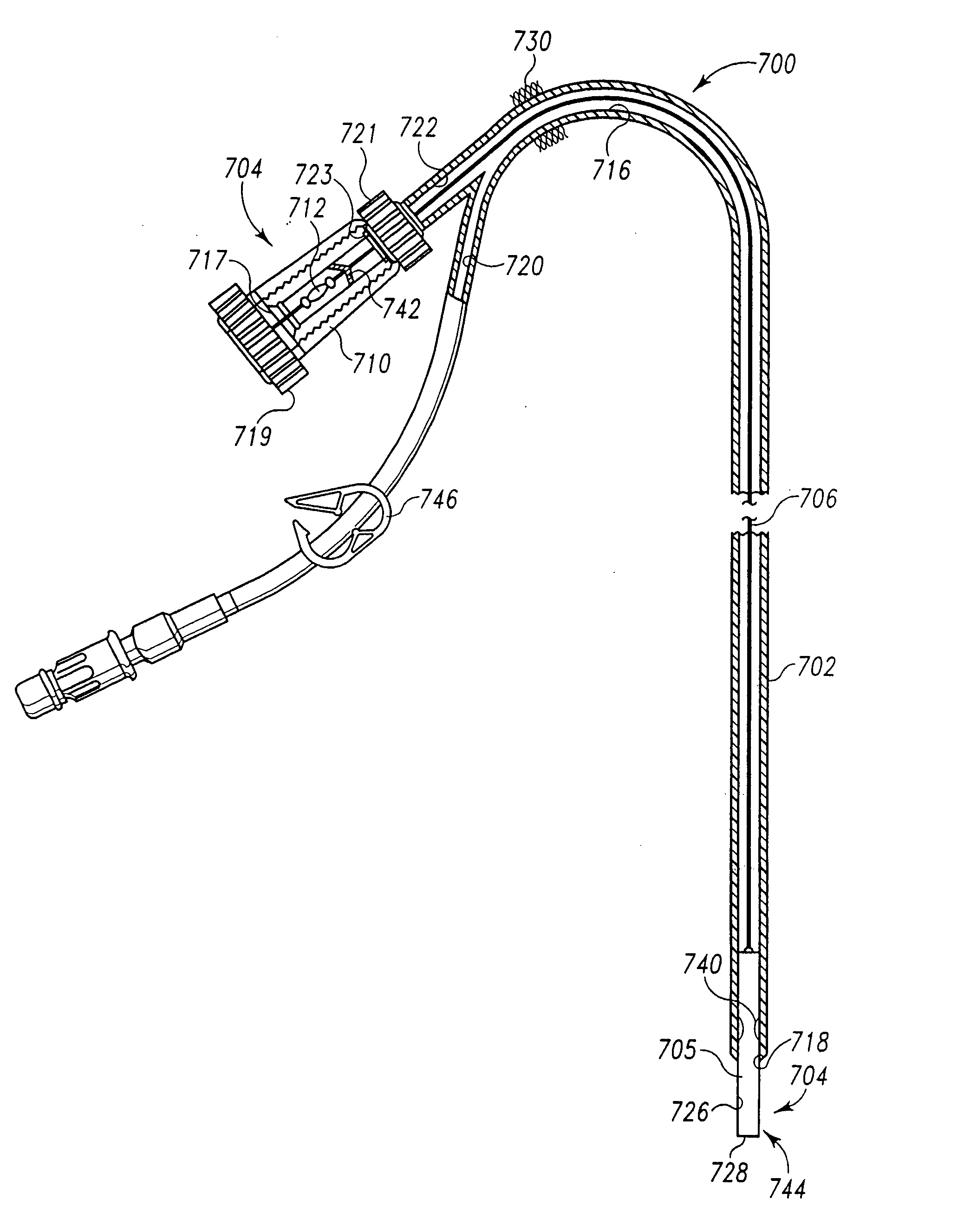
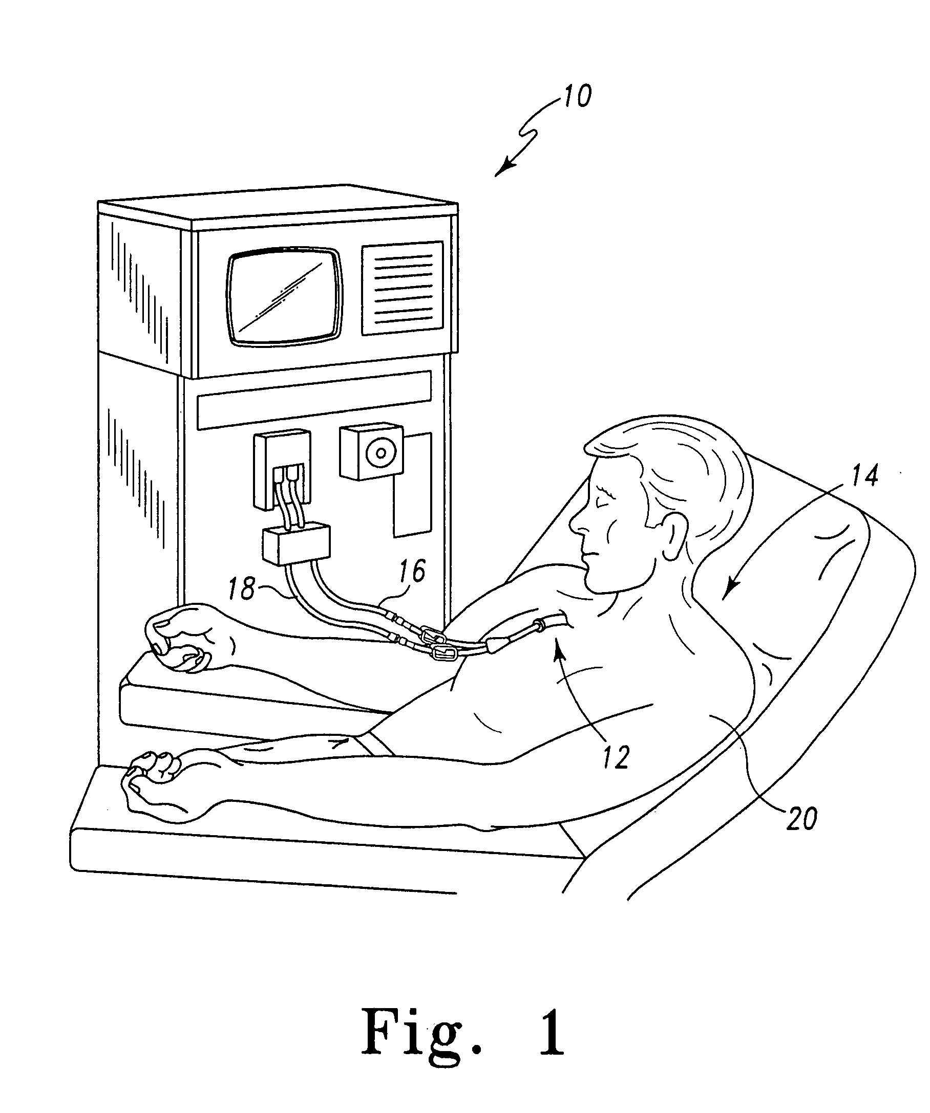
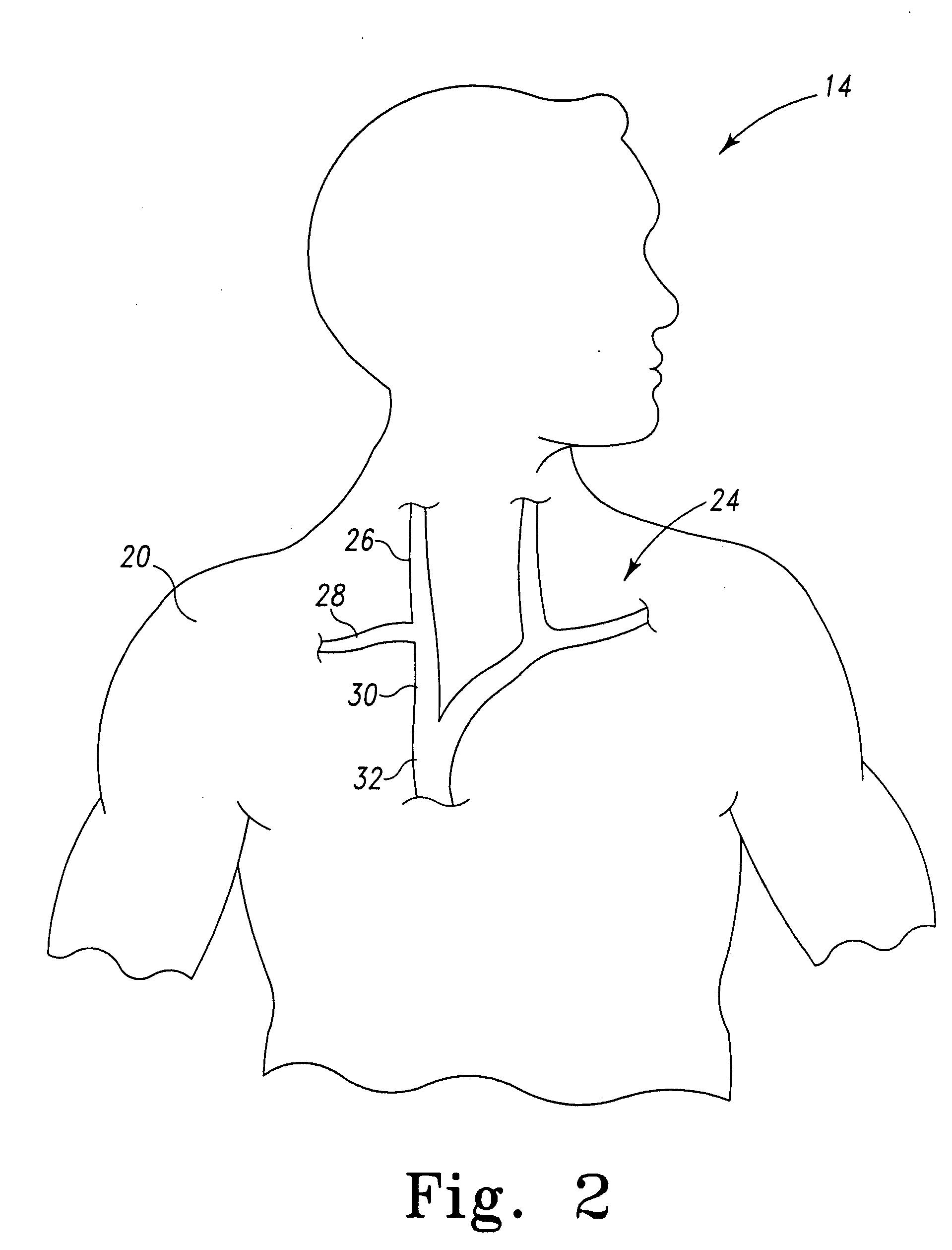
[0105] Referring now to FIG. 1, there is shown a hemodialysis machine 10 to which is attached a long-term catheter system 12 which incorporates the features of the present invention therein. The catheter system 12 is inserted in a patient's body 14. The hemodialysis machine 10 includes an inlet line 16 and an outlet line 18 which are each in fluid communication with the catheter system 12. The body 14 includes skin, generally indicated by the reference numeral 2...


PUM


Abstract

A catheter system includes a guide catheter having a lumen defining a distal orifice. The catheter system further includes a conduit segment positioned within the lumen and movable between (i) an upper position at which the conduit segment is entirely contained within the lumen of the guide catheter, and (ii) a lower position at which the conduit segment extends through the distal orifice so as to be partially positioned outside of the guide catheter. The catheter system further includes an actuator wire positioned within the lumen of the guide catheter and coupled to the conduit segment. Movement of the actuator wire causes movement of the conduit segment.

Description

[0001] This application is a continuation-in-part of application Ser. No. 10 / 006,799, filed on Dec. 4, 2001, and which will issue on Jun. 1, 2004 as U.S. Pat. No. 6,743,218. And the above-identified patent application Ser. No. 10 / 006,799 is a continuation-in-part of both (i) application Ser. No. 09 / 716,815, filed on Nov. 20, 2000 (now U.S. Pat. No. 6,723,084), and (ii) application Ser. No. 09 / 716,308, filed on Nov. 20, 2000 (now U.S. Pat. No. 6,585,705). And further, each of the above-identified patent application Ser. Nos. 09 / 716,815 and 09 / 716,308 is a continuation-in-part of application Ser. No. 09 / 443,876, filed on Nov. 19, 1999 (now U.S. Pat. No. 6,475,207), which in turn is a continuation-in-part of application Ser. No. 09 / 246,831, filed on Feb. 8, 1999 (now U.S. Pat. No. 6,190,371), which in turn claims the benefit of U.S. Provisional Application Ser. No. 60 / 116,017, filed Jan. 15, 1999. The disclosures of each of the above-identified patent applications and patents are hereb...

Claims


Application Information

Patent Timeline
IPC IPC(8): A61M1/16A61M1/36A61M25/01
CPCA61M1/16A61M1/3659A61M25/0194
Inventor MAGINOT, THOMAS J.MAGINOT, PAUL J.
Owner CATHLOGIC
Why Eureka
Try Eureka