Non-penetrating filtration surgery

a filtration surgery and laser ablation technology, applied in laser surgery, medical science, surgery, etc., can solve the problems of not being fine enough for some patients and/or protocols, preventing the practical use of low-depth laser ablation, and thermal damage to the membrane and/or other eye tissue does not heal as readily, so as to reduce or eliminate the scanning of the laser. , the effect of reducing the degree of safety

Active Publication Date: 2005-05-05
I OPTIMA LTD
View PDF20 Cites 60 Cited by
  • Summary
  • Abstract
  • Description
  • Claims
  • Application Information

AI Technical Summary

Benefits of technology

[0013] An advantage of monitoring using a human or automatic visual system is that the ablation at a particular location on the eye can be stopped as soon as the aqueous humor starts percolating out, without requiring an optional self-limiting behavior of the a laser beam to take effect.
[0014] An aspect of some embodiments of the invention relates to using a sensor, for example, an automatic vision system for monitoring a non-penetrating filtration procedure. In one embodiment of the invention, the vision system detects percolation of liquid from the ablated sclera or cornea, thus identifying that ablation at the percolating point should be stopped. Optionally, this allows a greater degree of safety. Alternatively or additionally, the vision system controls the scanner (or laser) to reduce or eliminate the scanning of the laser at some points, while continuing the scanning at other points in the eye.

Problems solved by technology

While the thickness of the percolation is dependent on the time between pulses, practical reasons, such as laser pulse rate, thermal damage and shock wave damage potentially caused by the laser pulse transfer generally prevent the practical use of low (e.g., micron) ablation depth lasers such as the Excimer and Er:YAG for the application of ablation.
While this laser does have some degree of flexibility the minimum ablation depth (where a minimum of charring is produced) is about 30 to 50 microns, which may not be fine enough for some patients and / or protocols.
In addition, it should be noted that unlike in skin applications, thermal damage to the membrane and / or other eye tissue does not heal as readily and is more likely to scar, for example due to the lack of underlying healing tissue.

Method used


Image

  • Non-penetrating filtration surgery
  • Non-penetrating filtration surgery
  • Non-penetrating filtration surgery

Examples


Embodiment Construction

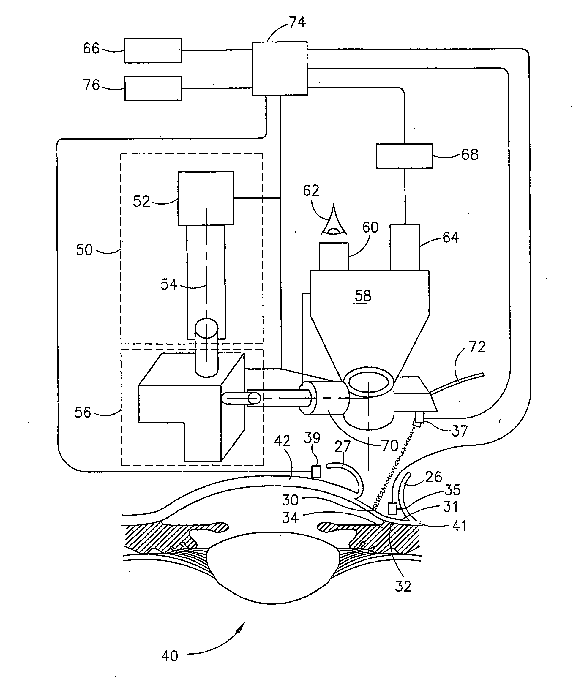
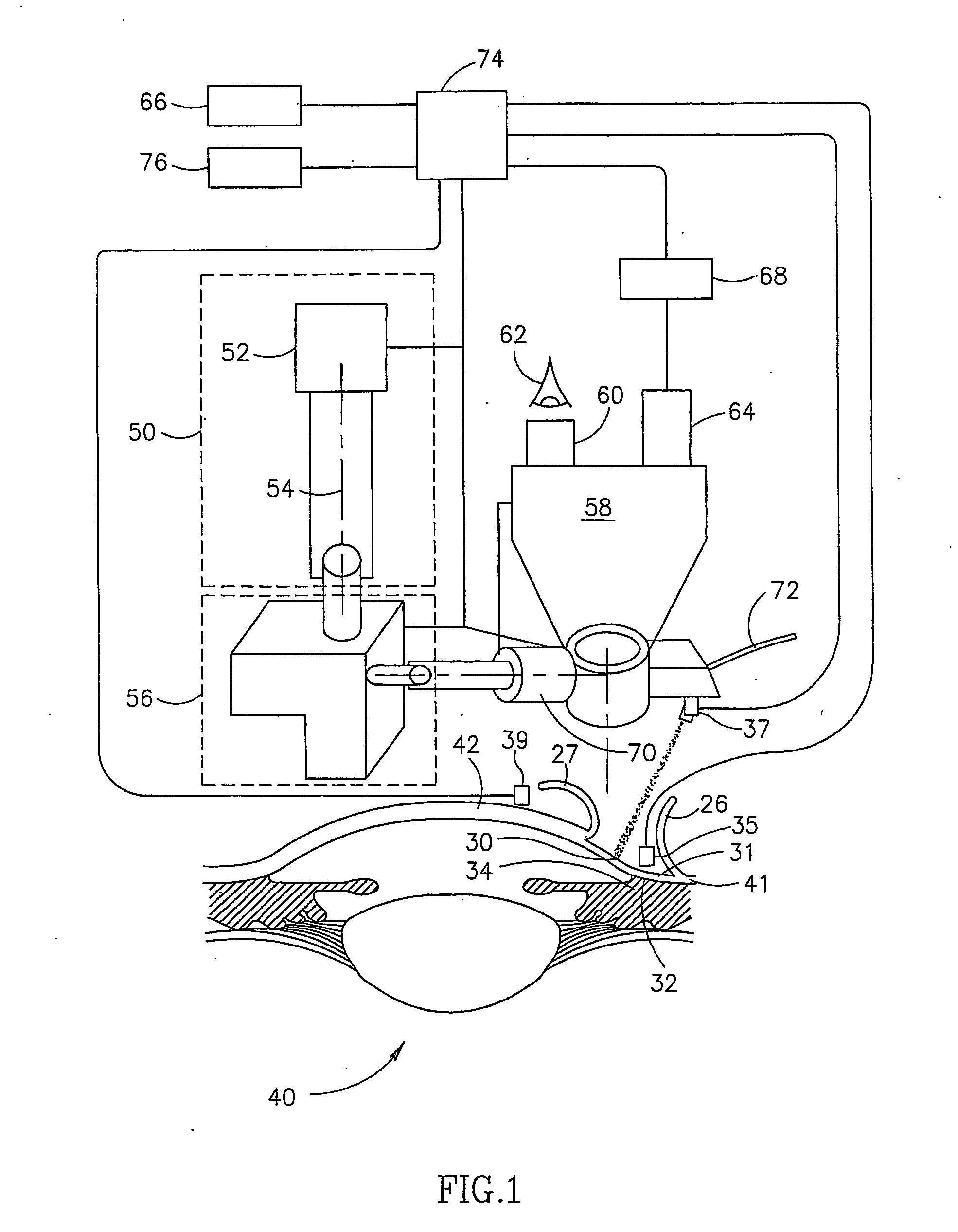
[0058]FIG. 1 is a schematic illustration of an exemplary ophthalmologic ablation system 50, during a non-penetrating filtration procedure in accordance with an exemplary embodiment of the invention.

[0059] Referring first to an eye 40, an exemplary filtration procedure using system 50 comprises ablating parts of an area 31 of a sclera 41 and / or a cornea 42 in an area 30. Some of the ablation is directed to those areas overlying a Schlemm's canal 34 and / or trabecular meshwork 32. The size of area 30 is exaggerated in FIG. 1, as in many procedures, area 30 is significantly smaller than area 31 and may comprise substantially only the boundary area between cornea 42 and sclera 41 that overlies the Schlemm's canal. In some procedures, however, a larger portion of the cornea may be ablated. Optionally, a scanner is used to scan a laser spot over an area of the sclera larger than the spot. A more detailed description of an exemplary filtration procedure and an exemplary scanner is provided...


PUM


Abstract

Apparatus for ophthalmic surgery, especially non-penetrating filtration surgery, comprising a laser source that ablates sclera tissue at steps of intermediate thickness. Optionally, the beam is scanned using a scanner and its results viewed using an ophthalmic microscope.

Description

RELATED APPLICATIONS [0001] This application is a continuation in part of PCT PCT / IL00 / 00263, filed May 8, 2000 in the Israel receiving office and which designates the US, the disclosure of which is incorporated herein by reference. This application also claims the benefit under 119(e) of 60 / 331,402, filed Nov. 15, 2001.FIELD OF THE INVENTION [0002] The present invention is related to the field of Glaucoma treatment using laser ablation. BACKGROUND OF THE INVENTION [0003] Glaucoma is an optical neuropathy associated with increased intraocular pressure. The mechanism of the disease is not fully understood. However, the most effective therapy appears to be reducing the intraocular pressure, for example using medication or implants. Further damage to the optic nerve is thus prevented or reduced. [0004] One procedure that has been suggested is non-penetrating trabeculectomy, in which a portion of the sclera overlying the Schlemm's canal is removed, allowing aqueous humor to leave the ey...

Claims


Application Information

Patent Timeline
Patent Type & Authority Applications(United States)
IPC IPC(8): A61F9/007A61F9/008A61B18/20
CPCA61F9/00802A61F9/00821A61F9/00825A61F2009/00897A61F2009/00868A61F2009/00872A61F2009/00891A61F2009/00865
Inventor SLATKINE, MICHAELASSIA, EHUDHAREL, ALEXSHARGIL, ADI
Owner I OPTIMA LTD
Why Eureka
Try Eureka